I have home automation implemented at my house that allows me to control and monitor things remotely (lights, cameras, etc). We were on a trip last week when my wife got a call after dinner from a neighbor who asked if we sitting home in the dark. That day there were high winds in the neighborhood and apparently there was a power outage in our area. The neighbor did not realize we were traveling, so she called to commiserate.
I then started to receive alerts on my phone from my cable provider and all of my cloud connections to let me know that everything was offline. I verified that I could not connect to anything at my house. The power was only out for about 3 hours and I got notifications when network connectivity had been restored. My IP cameras were all working correctly and all devices had reconnected, but since it was at night I could see that my exterior garage lights and entry door light were not on. The exterior cameras were operating with infrared so I still had visibility. Unfortunately, all of the things that I could do remotely (reset and re-pair the hub and the switch) did not work. The state of the switch was responding to commands, but the lights were not operating.
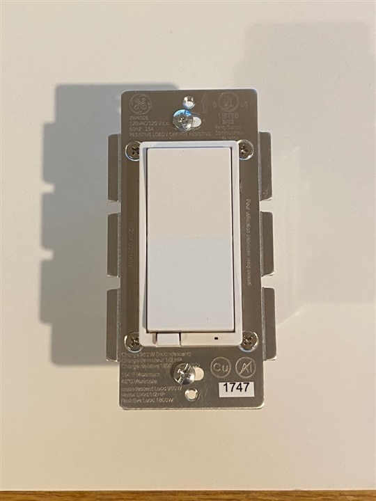
When we got home 5 days later, I saw that the blue LED on the switch was blinking indicating a fault condition (normally it tracks the state of the switch). The switch also did not operate manually when I pressed "on" and "off" on the paddle. The switch is a GE ZW4005 that I bought from Fry's Electronics about 4 years ago (before they went out of business). At that time I had planned to create a Z-Wave mesh and had bought a couple of wall switches and a Samsung hub. I never got around to implementing the mesh - I actually only used the one switch and did not acquire other sensors as I had planned, but this switch has been working reliably.
Searching the internet, I found that these particular switches are known to be susceptible to power surges. I thought this would be a good opportunity to learn about the construction of the switch and look for the cause of the failure. And thought it would be a good thing to share.
Well it turns out that before I got started, I found that Shahriar (The SIgnal Path Channel on YouTube) had already done an autopsy a couple of years ago for the same switch and failure mode. I thought that I'd share his video rather than try to create one of my own. Here is the link: Teardown & Repair of a Z-Wave GE ZW4005 Home Automation Wall Relay Switch. The failure is is an electrolytic capacitor in the power supply output.
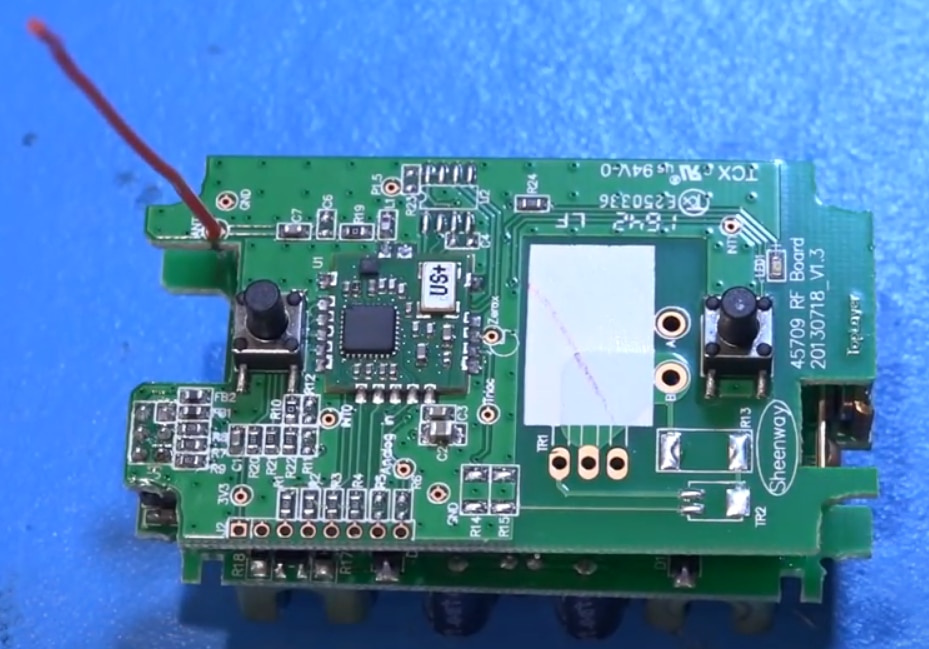
Here's a picture of the switch that I replaced and some images that I captured from Shahriar's video. It's a good video, but he does use the terms Z-Wave and ZigBee interchangeably which is not correct - although the controller might be programmable to do either protocol. There is also a frequency difference.

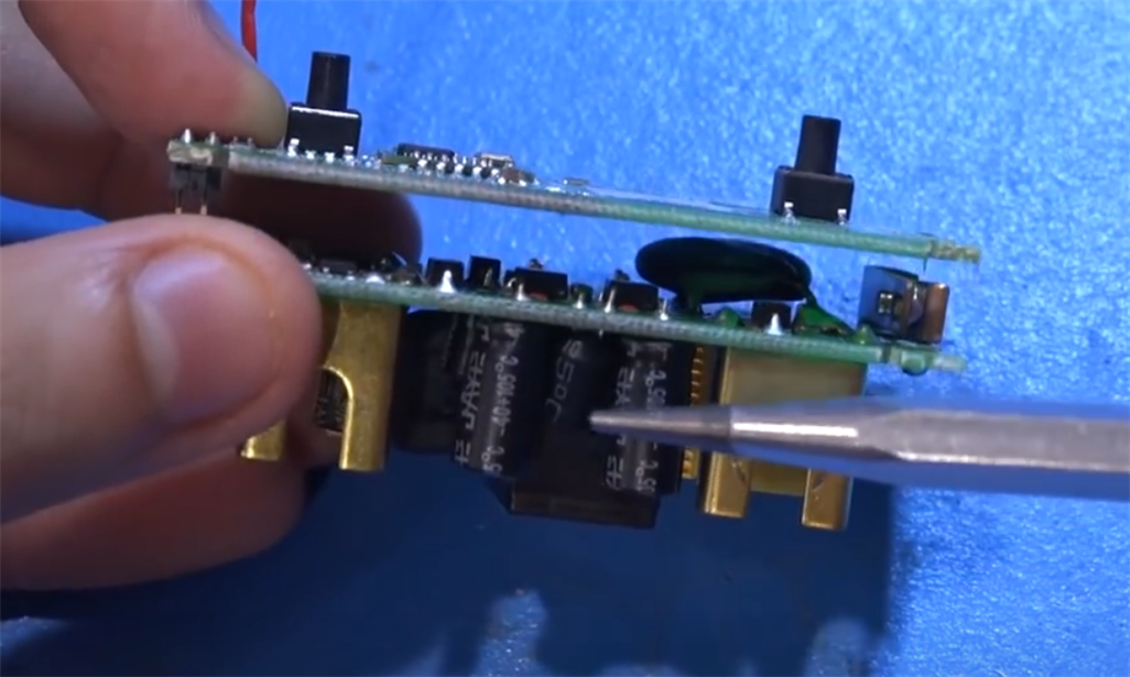
The switch is implemented as a stack of two boards - the logic/control/radio board and the board with the power supply and AC relay.

Apparently, the weak link is the 10UF cap in the output of the power circuit. He is pointing at it with the tweezers.


Power Supply Schematic with bad cap circled.

I'm debating whether or not to repair the switch power supply. I have half-a-mind to see if the logic board is operating and maybe use it for a remote controlled switch for a DC application.

-

baldengineer
-
Cancel
-
Vote Up
0
Vote Down
-
-
Sign in to reply
-
More
-
Cancel
Comment-

baldengineer
-
Cancel
-
Vote Up
0
Vote Down
-
-
Sign in to reply
-
More
-
Cancel
Children