element14 Community
element14 Community
    Register Log In
  • Site
  • Search
  • Log In Register
  • Members
    Members
    • Benefits of Membership
    • Achievement Levels
    • Members Area
    • Personal Blogs
    • Feedback and Support
    • What's New on element14
  • Learn
    Learn
    • Learning Center
    • eBooks
    • STEM Academy
    • Webinars, Training and Events
    • Learning Groups
  • Technologies
    Technologies
    • 3D Printing
    • Experts & Guidance
    • FPGA
    • Industrial Automation
    • Internet of Things
    • Power & Energy
    • Sensors
    • Technology Groups
  • Challenges & Projects
    Challenges & Projects
    • Design Challenges
    • element14 presents
    • Project14
    • Arduino Projects
    • Raspberry Pi Projects
    • Project Groups
  • Products
    Products
    • Arduino
    • Dev Tools
    • Manufacturers
    • Raspberry Pi
    • RoadTests & Reviews
    • Avnet Boards Community
    • Product Groups
  • Store
    Store
    • Visit Your Store
    • 'Choose another store...'
      • Europe
      •  Austria (German)
      •  Belgium (Dutch, French)
      •  Bulgaria (Bulgarian)
      •  Czech Republic (Czech)
      •  Denmark (Danish)
      •  Estonia (Estonian)
      •  Finland (Finnish)
      •  France (French)
      •  Germany (German)
      •  Hungary (Hungarian)
      •  Ireland
      •  Israel
      •  Italy (Italian)
      •  Latvia (Latvian)
      •  
      •  Lithuania (Lithuanian)
      •  Netherlands (Dutch)
      •  Norway (Norwegian)
      •  Poland (Polish)
      •  Portugal (Portuguese)
      •  Romania (Romanian)
      •  Russia (Russian)
      •  Slovakia (Slovak)
      •  Slovenia (Slovenian)
      •  Spain (Spanish)
      •  Sweden (Swedish)
      •  Switzerland(German, French)
      •  Turkey (Turkish)
      •  United Kingdom
      • Asia Pacific
      •  Australia
      •  China
      •  Hong Kong
      •  India
      •  Korea (Korean)
      •  Malaysia
      •  New Zealand
      •  Philippines
      •  Singapore
      •  Taiwan
      •  Thailand (Thai)
      • Americas
      •  Brazil (Portuguese)
      •  Canada
      •  Mexico (Spanish)
      •  United States
      Can't find the country/region you're looking for? Visit our export site or find a local distributor.
  • Translate
  • Profile
Internet of Things
  • Technologies
  • More
Internet of Things
Blog Driving BIG loads with your micro controller - no isolation
  • Blog
  • Forum
  • Documents
  • Events
  • Polls
  • Members
  • Mentions
  • Sub-Groups
  • Tags
  • More
  • Cancel
  • New
Internet of Things requires membership for participation - click to join
Blog Post Actions
  • Subscribe by email
  • More
  • Cancel
  • Share
  • Subscribe by email
  • More
  • Cancel
Group Actions
  • Group RSS
  • More
  • Cancel
Engagement
  • Author Author: peteroakes
  • Date Created: 5 Aug 2014 3:15 AM Date Created
  • Views 599 views
  • Likes 1 like
  • Comments 2 comments
  • mosfet
  • bipolar
  • internet_of_things
  • relays
  • electronics
  • arduino
  • launchpad
  • powering
Related
Recommended

Driving BIG loads with your micro controller - no isolation

peteroakes
peteroakes
5 Aug 2014

Back to the base project The Electronic Referee


So you have done blinky with an LED on the board, Now what


You want to drive a BIG LED like a 12V, 10W variety or something, well how you going to do that, the micro certainly cant do it without help and a Relay will still need a driver


You want to drive a BIG Servo or other motor up to 24V, well how you going to do that, the micro certainly cant do it without help and a Relay will still need a driver


These and many other mysteries are out there and in this instance I have a solution for you
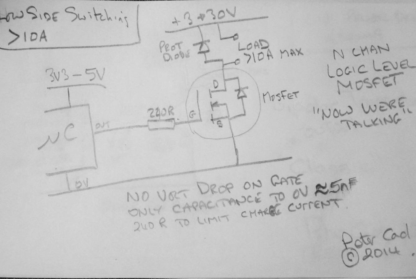
You don't have permission to edit metadata of this video.
Edit media
x
image
Upload Preview
image


The is a quick Peter Cad imageto go with the video, it is tested and works on a breadboard, go forth and experiment, any questions feel free to post in the forums or in the comments for this post


Enjoy

image

image


The next video dealing with OPTO Isolators can be found here Drive BIG things with added safety. OPTO Isolators

  • Sign in to reply
  • robogary
    robogary over 1 year ago

    I getcha, tho I'm far from an expert on the inner microscopic  workings of the FETS.  Normally I'm sticking the flyback diode ( and maybe an MOV and/or a snubber ) right on the terminals of the device being driven rather than at the MOSFET.  

    • Cancel
    • Vote Up 0 Vote Down
    • Sign in to reply
    • More
    • Cancel
  • D_Hersey
    D_Hersey over 9 years ago

    There are many semiconductors, when one considers extrinsics, they don't have to be from the III, V group, such as cadmium disulphide.  Silicon is popular mainly because SiO2 is insoluble in water, making MOSFETs possible.  The other reason silicon is so popular is because holes in Si behave almost like electrons.  This allows for complementary devices, PNP and P-channel.  Probably the concept of the FET is contemporaneous with that of the bipolar, but due to funding issues the more complicated bipolar was developed first.  AFIK it was patented about a decade-and-a half earlier.

    2.5 V uPs are here today.  The trend in uP supply potentials is ever downward.

    Actually, you described alpha gain, Hfe is beta gain which is the small-signal incremental gain.

    You can also modify the clamp to not be a hard clamp if you want your load to not 'knuckle under' the moment it de-energises.

    Collector saturation is about at (1V as a practical design point) 0.4V, so the product of that and the current through the saturated bipolar can be calculated.

    Bipolars are current-controlled current sources, FETs and triodes are voltage-controlled current sources.

    Most semiconductor manufactures are not recommending the gate resistor.  It slows things down.  CMOS can survive a dead short to either supply indefinitely.  It can certainly stand up to the moment it charges the gate.  The bulk resistance of the Si limits the current.

    If you are switching a MOSFET for PWM, a cheap soln is to use a PNP-NPN push-pull totem-pole follower.  Set ya' back about 10c.  Described here:  Practical Switching Power Supply Design (Motorola Series in Solid State Electronics): Martin C. Brown: 9780121370305: Am…

    Any MOSFET process is going to saturate at the bulk Si conductivity.  So, yeah, higher potential comes at the the cost of a higher Ron, that's how they do it.

    The intrinsic diode is parasitic and unavoidable and does not protect the transistor.  It can protect a neighboring transistor in certain situations such as a four-phase stepper.  Even then you should only use transistors whose reverse shunt diode is rated to run the same current as the conduction channel.  Regular ones only do half.

    You have omitted the alternative of using a voltage comparator as the first element in the gain chain.  Now, if your uP potential changes, you can just adjust the reference.  The computational burden of this soln. is also much lower.

    For relays that have coils that require about an ampere of current, especially for the beginner, it is far better to drive them with linear voltage regulators (with shutdown) rather than Qs.  Now our hero has over-current and over-temperature built in.  He can also chose between constant-current or constant voltage drive.

    You should mention that some coils require one amount of power to move and a lesser amount to hold.


    All of this nitpicking aside, I think you have made a great video!  Great introduction to switching amps.


    As an insomniac aside, let me state that if one is in a pinch and his power MOSFETs aren't capacious enough, he can parallel them, because at the power Q level, all of these type of transistor have a positive tempco.  Do not try this with bipolars, unless they are LM195s.  Actually, the MOSFET is LSI, constructed of many little Qs in series-shunt.

    Stay way away from the linear region when using MOSFETs in switchmode.  That positive tempco means that thermal runaway is a rather precipitant thing.  Un-drawn, sometimes, but important to the diode clamp mechanism you have illustrated is a capacitor across the supply local to the load and clamp diode.  The clamp diode must be electrically proximate to the load in order to protect.  The capacitor should be fast, robust and large enough to be storing an order of decimal magnitude more energy, at least, than the inductor being protected.  All of these connections need to be low-Z, if I am not being overly redundant.

    Also, going back to this gate resistor thing, insomnia obviously not abating.  If the goal is to produce an LPF, the problem is that gate capacitance is going to be a weakly-controlled parameter because the manufacturer is going to try to minimize it.  Thus, probably better to use an op-amp LPF and follow it with a Q.

    Another semi-omission is a shutoff resistor between the control terminal and the source of the MOSFET.  We like to put those in in case the output driving the Q is disconnected or inadvertently goes tri-state or input mode or is high-Z on power-up.  In the case of no signal, this shuts off the transistor, inactivating the load.  Go w/ 75K, say.

    The Nobel Prize in Physics 1956

    • Cancel
    • Vote Up 0 Vote Down
    • Sign in to reply
    • More
    • Cancel
element14 Community

element14 is the first online community specifically for engineers. Connect with your peers and get expert answers to your questions.

  • Members
  • Learn
  • Technologies
  • Challenges & Projects
  • Products
  • Store
  • About Us
  • Feedback & Support
  • FAQs
  • Terms of Use
  • Privacy Policy
  • Legal and Copyright Notices
  • Sitemap
  • Cookies

An Avnet Company © 2023 Premier Farnell Limited. All Rights Reserved.

Premier Farnell Ltd, registered in England and Wales (no 00876412), registered office: Farnell House, Forge Lane, Leeds LS12 2NE.

ICP 备案号 10220084.

Follow element14

  • X
  • Facebook
  • linkedin
  • YouTube