This post is about an interesting, low-cost sensor that doesn’t need much processing to use, and has some unique characteristics – a PVDF (polyvinylidene difluoride) Piezoelectric sensor. The sensors looks like a small strip of plastic, and can be used for detecting movement or vibrations even into ultrasound. Such devices can help sense in many practical, real-world scenarios. They are extremely sensitive, low cost and easy to use.
Some simple practical experiments with these sensors are described, finally looking at detecting ultrasound.
Introduction
Sensors will play a big role in IoE helping to identify what is happening in the real world. I was keen to try out PVDF sensors because I think they could have a lot of applications. For example, they could be used to identify when home appliances are in use (due to vibrations), such as a washing machine, or as movement detectors (sensing people walking on a floor) or glass breaking.
There is a general overview on Wikipedia, but in summary PVDF (also known as PVF2) is a plastic that, when suitably manufactured (it is stretched, heated and an electric field applied during manufacture), becomes a piezoelectric material, meaning that it can generate a charge when some force is applied to it. It appears that stretching orientates the molecules into a common direction, and the electric field (at a temperature close to melting point) further aligns the molecules from an electrical orientation standpoint.
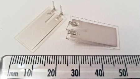
The PVDF sensor available from Farnell / Newark is a small sheet of the material with a layer of metal on each side and two crimped contacts (PVDF has a low melting point so be quick with the soldering iron). It is about the size of a small stamp.
There is a wealth of information for PVDF sensors here (in particular the Piezo Technical Manual on that page). It shows that PVDF has many applications including switches, impact, vibration and ultrasound.
Initial experiments
According to what I’d read, the voltage output from such sensors was quite high. The first step was to connect it up to the oscilloscope and see if this was the case, and if anything was measurable. It turns out the answer was Yes!
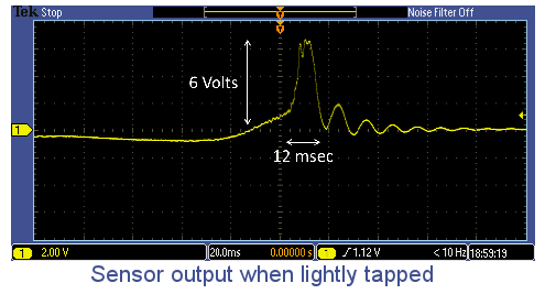
Here is the output when the sensor was lightly flicked – the amplitude was 6V.
This level of output could be interfaced to a microcontroller with no amplification needed, but some protection would be needed (either clamp with diodes, or (as shown in the technical document) limit the current with a series resistor).
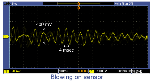
This was the output when gently blowing on the sensor from a few centimetres:
Again, this is quite a high voltage. It would not need much amplification to allow connection to a microcontroller.
Maximising Sensor Output
PVDF sensors generate a charge when mechanically stressed. It turns out that to get the maximum output from the sensor, the stress needs to be in a direction that depends on which axis of the sensor the film was stretched during manufacture. For the Farnell sensor the stretched direction is along its longest direction. The most convenient way to use the sensor for general vibration or impulse detection is to perform tensile stress in that direction. A sideways force can do that. In other words, if it is bent then you’ll get a high voltage out.
The reason that bending the PVDF sensor generates such a stress is that the sensor is being stretched on one side when flexed. Both sides need to be stretched for maximum output, and that can be achieved by having the PVDF film on some thickness of material, to move the center onto one side. The particular sensor used already has the film off-center as far as I can tell (it has a protective layer with a certain width on one side, but not the other).
Example Application
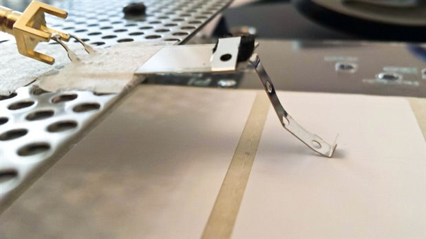
As a quick experiment it was decided to try to create an example application. Here the sensor was mounted with a springy metal end, to try and detect paper labels.
When the strip of labels is dragged across, a signal is clearly observed on the oscilloscope. However some processing would be needed, because even dragging across plain paper generates a signal. In fact, even a tap on the table would generate a signal. Clearly it is extremely sensitive.
Amplifying the Signal
The fact that it was so sensitive got me interested in seeing how the sensor could be used with yet more subtle disturbances.
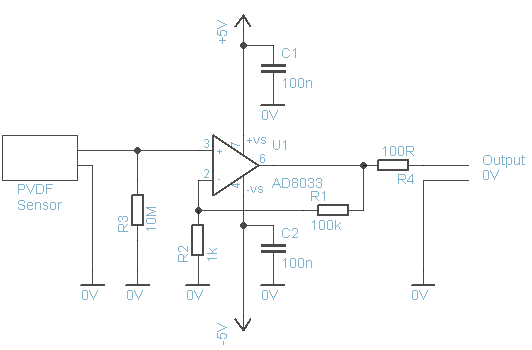
The circuit shown above was constructed. The op amp does have input protection up to some limit, but to protect against any accidental knocks to the sensor it would be good to use a series resistor (a few hundred ohms) to the input of the op amp, and diode clamps (two low leakage diodes like BAS116) connected from the input to +5V and from the input to -5V (both in the reverse biased direction).
The gain was set to 100. The amplifier functions from DC to several hundred kilohertz, so it needs a bit of care during construction. The circuit functioned, but, as expected, the high input impedance makes it very sensitive to pick up 50/60Hz mains hum too. Any mains cable placed close to the sensor will cause a signal to get picked up.
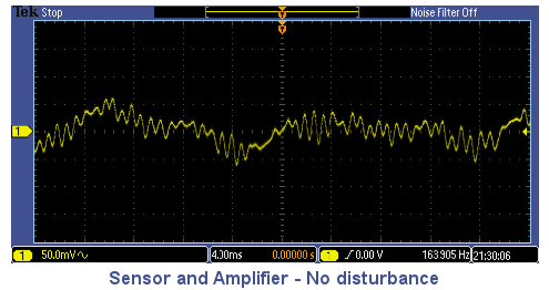
The oscilloscope trace below shows the result from placing the circuit in a biscuit tin (not fully enclosed because I didn’t make a hole for the cable). There is some source being picked up (40mV p-p output from the circuit) at about 1.3kHz – I couldn’t identify it (it may be a nearby equipment fan which I couldn’t switch off). At this level of sensitivity sounds are picked up by the PVDF sensor.
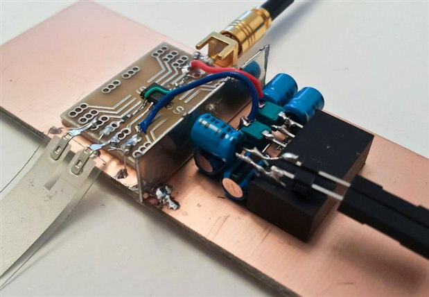
A high-pass filter or alternatively a notch filter could be used to reduce the effect. However, no high pass filter was used so I could see low frequency vibrations too. It was extremely sensitive. If placed on the floor so that the sensor was gently pressing on the desk (as shown in the photo above), a light touch of the desk would result in a signal. On the floor, it could detect anyone walking nearby.
For a real application, as mentioned, some filtering would be needed to expose just the frequencies of interest. The sensor easily picks up mains hum (shielded versions are available). The filtering could be analog, or alternatively it could be digital once the signal has converted using an ADC.
Experimenting with Ultrasound sensing
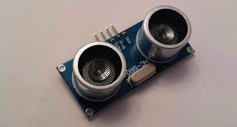
One application for PVDF sensors is ultrasound detection. PVDF can also be used for ultrasound generation but that was not explored here. To generate ultrasound I used a low cost ‘ping’ module and positioned it facing the PVDF sensor.
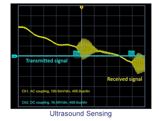
The output from the module was tapped (from the output) and observed on the oscilloscope. For the PVDF sensor, the same op amp circuit as before was used. It was positioned so that the end of the PVDF sensor was not touching anything. The traces here show the captured result. For each brief 40kHz burst from the ping module, a clear signal was picked up (the signal is on top of 50Hz mains hum here; I performed this test outside of the biscuit tin. A 50/60Hz notch circuit could filter it out if ultrasound was the only signal of interest).
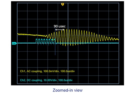
The image below shows a zoomed-in view of the signals:
It is possible to see that the ping module sends a burst of 8 pulses to the ultrasound transmitter. Resonance causes the generated signal to rise in amplitude; although the distance was not accurately measured the transmitter and the sensor were positioned quite close (a few centimeters) from each other and that agrees with the time difference between the signals (the trace is marked from the end of the burst and the peak of the received signal in the oscilloscope capture above).
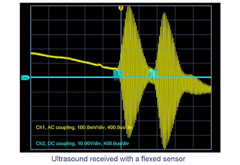
According to the document mentioned earlier, ultrasound sensing works best when the PVDF film is bent into a curved shape. So, the sensor was flexed slightly and the test was reattempted.
This time, the output from the circuit was far greater; almost 1V p-p from a distance of about 2cm. It was still easily detectable from 30 cm away. I didn’t try further.
Summary
The above only touches on some aspects of PVDF sensors, but there are many interesting use-cases that could be explored. It can be seen that very little interfacing circuitry is needed to make use of these sensors!


Top Comments
-

Instructorman
-
Cancel
-
Vote Up
+2
Vote Down
-
-
Sign in to reply
-
More
-
Cancel
Comment-

Instructorman
-
Cancel
-
Vote Up
+2
Vote Down
-
-
Sign in to reply
-
More
-
Cancel
Children