


When you try to measure light intensity with a photodiode, you have to build some circuitry around it.
There are several ways to do that. In this post, I'm investigating TI's application note MSPM0 Subsystem Design Transimpedance Amplifier.
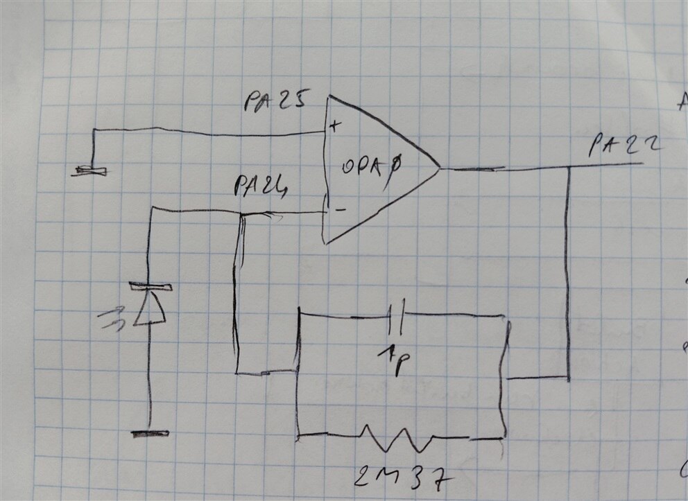
This is an interesting circuit. Because the OpAmp clamps the diode voltage to 0 V (same value as positive input), the only way the energy in the diode can escape, is as current. That current has to come from the output, via the feedback resistor (it can't come from the OpAmp input, because that's the same level as the other side of the diode: ground). That also means that the output has to be a higher voltage than ground: ground + (current * resistance). And that's something the ADC can then measure. See here for a better explanation.
|
The OpAmp used in this design is one of the two that are embedded in the MSPM0 silicon. They are rail-to-rail chopper types (TI calls them zero-drift, zero-crossover chopper operational amplifiers). The microcontroller gives you control for:
|
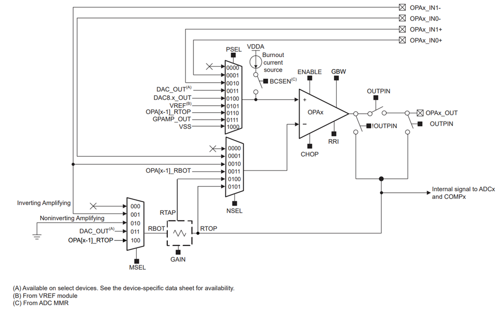
In the photodiode design, we use the OpAmp in a very classic way:
- the in- and outputs are routed to external pins
- chopper off
- programmable gain off
- rail-to-rail off
- high bandwidth (TI uses different setting in the transimpedance example and the out-of-box source. I used the settings of the latter)
The feedback loop is built up by external components (see schematic drawing at the top of this post). TI has done the homework to specify them based on the specs of the Vishay VEMD4110X01 that's mounted on the launchpad. The capacitance of the diode is dependent on the voltage over it. In our case, there is 0V over the diode, and capacitance in that case is 5 pF. The max current is in the low single digit µA.
Let's assume that the diode generates 1 µA. With the 2.37 MΩ resistor in the feedback loop, that would give an OpAmp output of 2.37 V.
The rest of the design is uneventful. The MSPM0 ADC input is muxed to the same pin that's connected to the OpAmp output (there is an option to mux it internally on silicon too). The reference voltage is VDDA (analog VDD, on this launchpad the common 3.3 V). The ADC is set to single shot mode, and gets triggered by one of the timers.
That's all.

