element14 Community
element14 Community
    Register Log In
  • Site
  • Search
  • Log In Register
  • Community Hub
    Community Hub
    • What's New on element14
    • Feedback and Support
    • Benefits of Membership
    • Personal Blogs
    • Members Area
    • Achievement Levels
  • Learn
    Learn
    • Ask an Expert
    • eBooks
    • element14 presents
    • Learning Center
    • Tech Spotlight
    • STEM Academy
    • Webinars, Training and Events
    • Learning Groups
  • Technologies
    Technologies
    • 3D Printing
    • FPGA
    • Industrial Automation
    • Internet of Things
    • Power & Energy
    • Sensors
    • Technology Groups
  • Challenges & Projects
    Challenges & Projects
    • Design Challenges
    • element14 presents Projects
    • Project14
    • Arduino Projects
    • Raspberry Pi Projects
    • Project Groups
  • Products
    Products
    • Arduino
    • Avnet Boards Community
    • Dev Tools
    • Manufacturers
    • Multicomp Pro
    • Product Groups
    • Raspberry Pi
    • RoadTests & Reviews
  • Store
    Store
    • Visit Your Store
    • Choose another store...
      • Europe
      •  Austria (German)
      •  Belgium (Dutch, French)
      •  Bulgaria (Bulgarian)
      •  Czech Republic (Czech)
      •  Denmark (Danish)
      •  Estonia (Estonian)
      •  Finland (Finnish)
      •  France (French)
      •  Germany (German)
      •  Hungary (Hungarian)
      •  Ireland
      •  Israel
      •  Italy (Italian)
      •  Latvia (Latvian)
      •  
      •  Lithuania (Lithuanian)
      •  Netherlands (Dutch)
      •  Norway (Norwegian)
      •  Poland (Polish)
      •  Portugal (Portuguese)
      •  Romania (Romanian)
      •  Russia (Russian)
      •  Slovakia (Slovak)
      •  Slovenia (Slovenian)
      •  Spain (Spanish)
      •  Sweden (Swedish)
      •  Switzerland(German, French)
      •  Turkey (Turkish)
      •  United Kingdom
      • Asia Pacific
      •  Australia
      •  China
      •  Hong Kong
      •  India
      •  Korea (Korean)
      •  Malaysia
      •  New Zealand
      •  Philippines
      •  Singapore
      •  Taiwan
      •  Thailand (Thai)
      • Americas
      •  Brazil (Portuguese)
      •  Canada
      •  Mexico (Spanish)
      •  United States
      Can't find the country/region you're looking for? Visit our export site or find a local distributor.
  • Translate
  • Profile
  • Settings
Internet of Things
  • Technologies
  • More
Internet of Things
Blog Old meets new, the 1-Wire Weather Station on the SPARK Core. (part 7)
  • Blog
  • Forum
  • Documents
  • Quiz
  • Events
  • Polls
  • Members
  • Mentions
  • Sub-Groups
  • Tags
  • More
  • Cancel
  • New
Join Internet of Things to participate - click to join for free!
  • Share
  • More
  • Cancel
Group Actions
  • Group RSS
  • More
  • Cancel
Engagement
  • Author Author: gpolder
  • Date Created: 13 May 2015 7:52 PM Date Created
  • Views 696 views
  • Likes 3 likes
  • Comments 1 comment
  • wifi
  • biquad
  • weather_station
  • 1-wire
  • spark_core
  • internet-of-things
  • iot
  • wireless
  • antenna
Related
Recommended

Old meets new, the 1-Wire Weather Station on the SPARK Core. (part 7)

gpolder
gpolder
13 May 2015

Its already some time ago that I wrote my previous post in this series (Old meets new, the 1-Wire Weather Station on the SPARK Core. (part 6)).

In the meantime I did a lot of tests using the solar pannel and different types of batteries and discharge schedules monitored by a bitscope/Raspberry Pi combination ( http://www.element14.com/community/roadTestReviews/1986 ).


Now its time to wrap up and mount everything together in a neat package which can be placed in the backyard. In order to do so a relaible WiFi connection is needed over this longer than usual distance. The SPARK CORE I'm using is equipped with a u.FL connector to which you can connect an external antenna with more gain than the standard chip antenna on the PCB. First tests on my desk were done with a simple wire antenna with a length of 1/4 of the wavelength (3 cm). For my backyard experiments I decided to build a BiQuad antenna. This type of antenna is very popular, lots of information can be found on the internet. My design is inspired by: De ultieme biquad Wifi antenne bouw pagina where you also can find drawings of the exact lengths and distances.


Building the WiFi BiQuad antenna

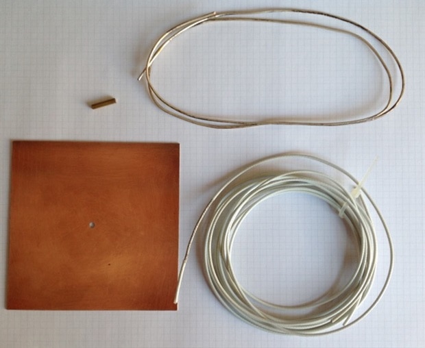
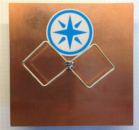
Here is a picture of the material I used. A piece of coper clad as base and reflector. On the backside I will mount the electronics. I had some silvered coper wire laying around. This will be used for the radiator, furthermore some ptfe isolated coax cable and a piece of brass tube.

image

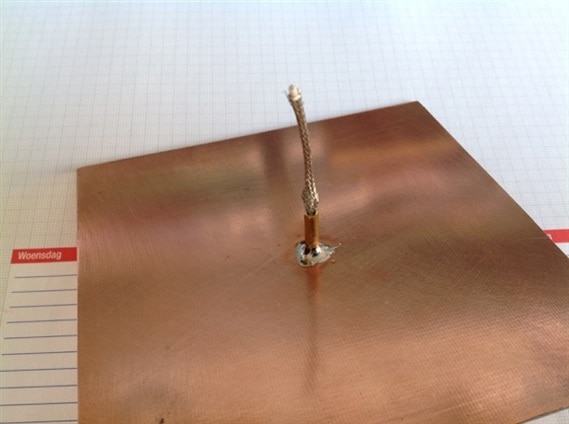
In the center of the plate a 3mm hole is drilled, and the brass tube is placed at 16 mm and soldered on both sides.

imageimageimage

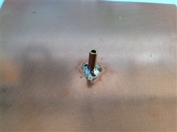
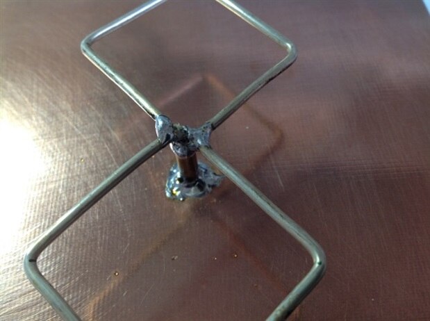
A pice of coax cable is soldered to the end of the brass tube.

imageimageimage

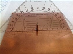
A pice of silvered copper wire is cut at 244 mm, and 8 pieces of 31 mm are marked.

image

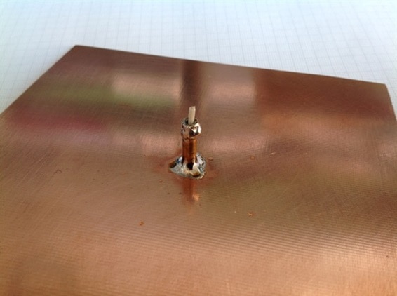
Then the radiator is bended.

image

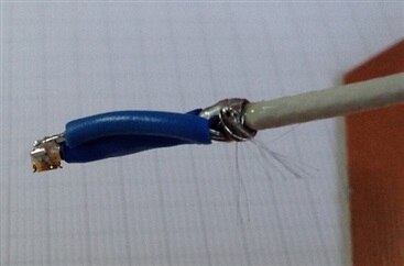
And soldered to the brass tube on one side and to the kernel of the coax on the other side.

imageimage

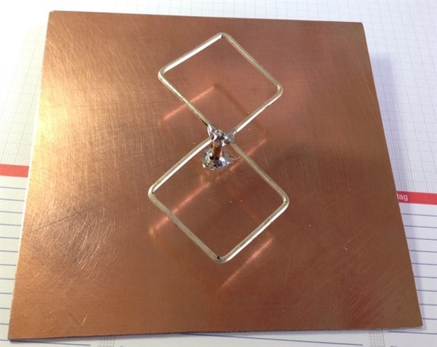
With this step the antenna is already finished. Simple isn't it?

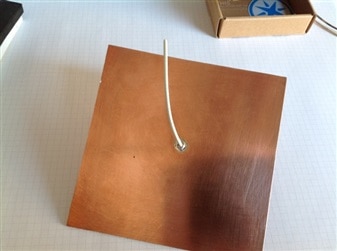
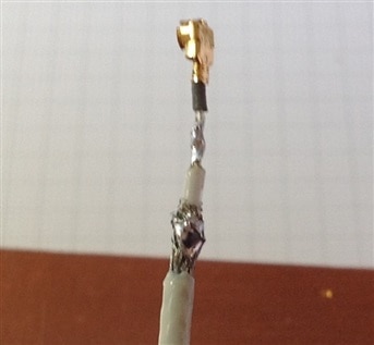
In order to connect the antenna to the SPARK CORE, a u.FL connector had to be connected to the other side of the coax cable.

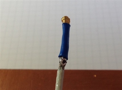
Due to the small size of this connector and the 'still' large diameter of the coax this was not a simple task. I took a simple WiFi antenna (66089-2406 - ANAREN - ANTENNA, 66089, 24C, 2400MHZ, U.FL | Farnell element14), cut the wire and soldered that to the kernel of the coax. And a small piece of wire connects the coax shield to the u.FL connector shield. Some heat shrink tubes act as isolator. I realize that this is not a good 50 ohm connection, but I don't see a better option. As you will see later in this blog the antenna functions very good, so I don't think this connection is a big problem.

imageimageimageimage


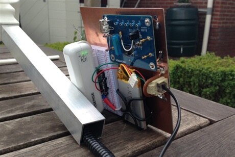
Mounting it all together

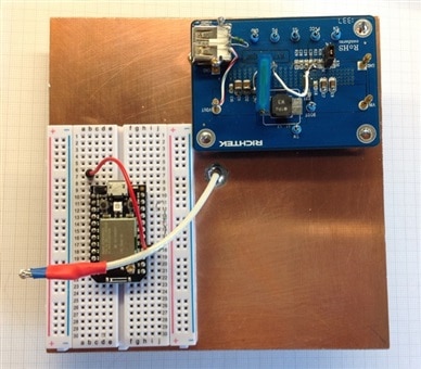
The electronics are mounted on the other side of the coper board, resulting in a neat compact unit.

The Richtek EVB_RT7275GQW Evaluation Board is soldered using some pieces of coper wire.

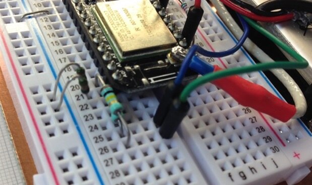
I decided to use the breadboard for the SPARK CORE, so that I easily can make modifications to the circuit.

imageimage

A RJ-11 connector connects the Weather station to the SPARK CORE.

image

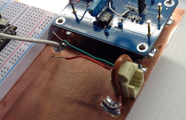
Isolated coper wires and a piece of foam are used to mount the LiPo battery.

imageimage

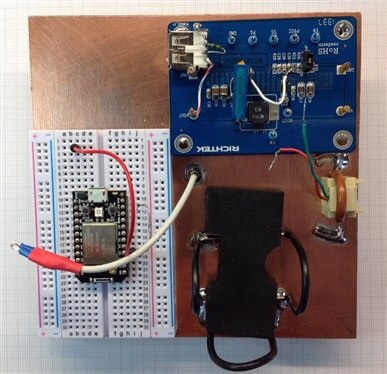
The input and output of the RichTek board are connected to to analog inputs, in order to monitor the Solar panel and power supply voltage.

Voltage dividers converts te max 21V input of the solar pannel to 3.3V which is the max input of the SPARK CORE.

image

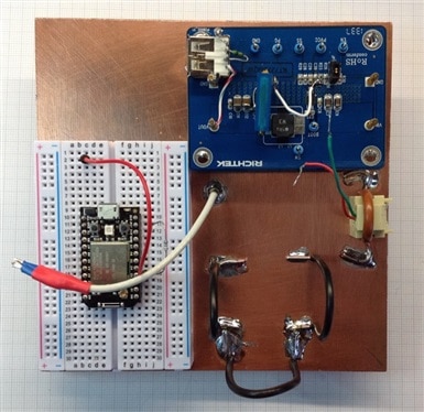
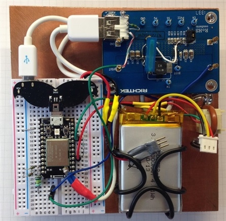
The front and backside of the final unit:

imageimage

Some test from my backyard at about 20m from the WiFi router showed very good results, The signal strength of the SPARK CORE was about 10 dB stronger than the signal from my smartphone. When you need real long distances you can combine the BiQuad antenna with a satellite parabole dish. joeman has a nice video on this (The specified item was not found.).

imageimage


The project is now almost ready, in my next and final post on this project I will put everything together and update the software.


Stay tuned.

Do not hesitate when you have questions.

  • Sign in to reply
  • Mustang65
    Mustang65 over 1 year ago

    Hi Gerrit, I know that this project was done years ago, but I just located it as I just found my Dallas 1wire Weather Station hiding in a box, without any of my original documentation. So I have the unit apart and looking at the circuit board I am trying to figure out which pins are which on the RJ11 connector. With the tab of the on the top looking into the opening side, and pin #1 is on the right, it looks like data is on pin #3 and pin #4 is ground. Also, it looks like pin #5's only function is to jumper between the pin #5 of each of the connectors as there is no other connection on them as I can see. I went through all your 7 write ups but was not able to locate the pin out for the RJ11. I do not want to fry the chips on the circuit board. Any assistance would be a great help. Oh, I decided to use a Pico W  opposed to using the Arduino or the ESP32. I will be making the PicoW a Stand alone AP and it will also send the data to a file on a Raspberry Pi in the house. I also have the Dallas 1 wire rain gauge also to connect. I live in Florida and I hope to get the unit mounted and the hardware/software up and running FAST as we are in Hurricane season now. Thank you in advance for any assistance you can give me. Don

    • Cancel
    • Vote Up 0 Vote Down
    • Sign in to reply
    • More
    • Cancel
element14 Community

element14 is the first online community specifically for engineers. Connect with your peers and get expert answers to your questions.

  • Members
  • Learn
  • Technologies
  • Challenges & Projects
  • Products
  • Store
  • About Us
  • Feedback & Support
  • FAQs
  • Terms of Use
  • Privacy Policy
  • Legal and Copyright Notices
  • Sitemap
  • Cookies

An Avnet Company © 2025 Premier Farnell Limited. All Rights Reserved.

Premier Farnell Ltd, registered in England and Wales (no 00876412), registered office: Farnell House, Forge Lane, Leeds LS12 2NE.

ICP 备案号 10220084.

Follow element14

  • X
  • Facebook
  • linkedin
  • YouTube