element14 Community
element14 Community
    Register Log In
  • Site
  • Search
  • Log In Register
  • Community Hub
    Community Hub
    • What's New on element14
    • Feedback and Support
    • Benefits of Membership
    • Personal Blogs
    • Members Area
    • Achievement Levels
  • Learn
    Learn
    • Ask an Expert
    • eBooks
    • element14 presents
    • Learning Center
    • Tech Spotlight
    • STEM Academy
    • Webinars, Training and Events
    • Learning Groups
  • Technologies
    Technologies
    • 3D Printing
    • FPGA
    • Industrial Automation
    • Internet of Things
    • Power & Energy
    • Sensors
    • Technology Groups
  • Challenges & Projects
    Challenges & Projects
    • Design Challenges
    • element14 presents Projects
    • Project14
    • Arduino Projects
    • Raspberry Pi Projects
    • Project Groups
  • Products
    Products
    • Arduino
    • Avnet Boards Community
    • Dev Tools
    • Manufacturers
    • Multicomp Pro
    • Product Groups
    • Raspberry Pi
    • RoadTests & Reviews
  • About Us
  • Store
    Store
    • Visit Your Store
    • Choose another store...
      • Europe
      •  Austria (German)
      •  Belgium (Dutch, French)
      •  Bulgaria (Bulgarian)
      •  Czech Republic (Czech)
      •  Denmark (Danish)
      •  Estonia (Estonian)
      •  Finland (Finnish)
      •  France (French)
      •  Germany (German)
      •  Hungary (Hungarian)
      •  Ireland
      •  Israel
      •  Italy (Italian)
      •  Latvia (Latvian)
      •  
      •  Lithuania (Lithuanian)
      •  Netherlands (Dutch)
      •  Norway (Norwegian)
      •  Poland (Polish)
      •  Portugal (Portuguese)
      •  Romania (Romanian)
      •  Russia (Russian)
      •  Slovakia (Slovak)
      •  Slovenia (Slovenian)
      •  Spain (Spanish)
      •  Sweden (Swedish)
      •  Switzerland(German, French)
      •  Turkey (Turkish)
      •  United Kingdom
      • Asia Pacific
      •  Australia
      •  China
      •  Hong Kong
      •  India
      •  Korea (Korean)
      •  Malaysia
      •  New Zealand
      •  Philippines
      •  Singapore
      •  Taiwan
      •  Thailand (Thai)
      • Americas
      •  Brazil (Portuguese)
      •  Canada
      •  Mexico (Spanish)
      •  United States
      Can't find the country/region you're looking for? Visit our export site or find a local distributor.
  • Translate
  • Profile
  • Settings
Internet of Things
  • Technologies
  • More
Internet of Things
Documents Sailing Auto Pilot - Competition - Ready For Tomorrow 2022
  • Blog
  • Forum
  • Documents
  • Quiz
  • Events
  • Polls
  • Members
  • Mentions
  • Sub-Groups
  • Tags
  • More
  • Cancel
  • New
Join Internet of Things to participate - click to join for free!
Actions
  • Share
  • More
  • Cancel
Engagement
  • Author Author: e14phil
  • Date Created: 28 Feb 2022 8:57 AM Date Created
  • Last Updated Last Updated: 29 Nov 2022 2:03 PM
  • Views 16719 views
  • Likes 16 likes
  • Comments 61 comments
Related
Recommended

Sailing Auto Pilot - Competition - Ready For Tomorrow 2022

Farnell partners with sailor Alberto Riva to redevelop a Nautical Autopilot image

Alberto Riva is a multi-competition winning skipper who always had a passion for sailing since he was a child.

With the support of many different sponsors, he has sailed on a variety of boats from smaller centreboard boats to 70ft long flying trimarans, on board of which he competed many different regattas.i

He now has an eye on a new dream: the Mini Transat - a 4050 nautical miles solo race on the smallest offshore racing boats at only 6.50m long. A challenge that requires not only competence and resilience, but also a sound mind.

You don't have permission to edit metadata of this video.
Edit media
x
image
Upload Preview
image

Far from being only a sailing passionate and competitor, indeed, Alberto is also a trained engineer who worked as data analyst and on-board electronics expert for the preparation of other racing boats. With a master in nanotechnologies, he also developed an auto-pilot board during his studies

.image
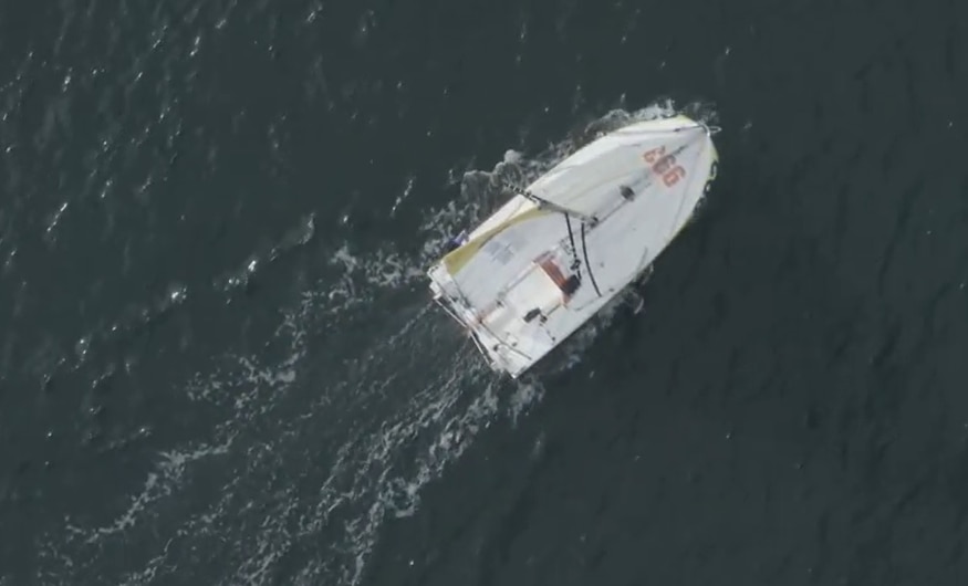
The auto-pilot is an element that he defines “his best friend” during sailing, as it allows him to leave the wheel and rest or focus on weather conditions especially on demanding regattas like the Transat, where one-person sailing and no phone/computer or technical support aside from tracking are the main requirements.
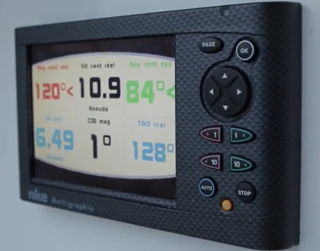
image

Interface for AutoPilot 

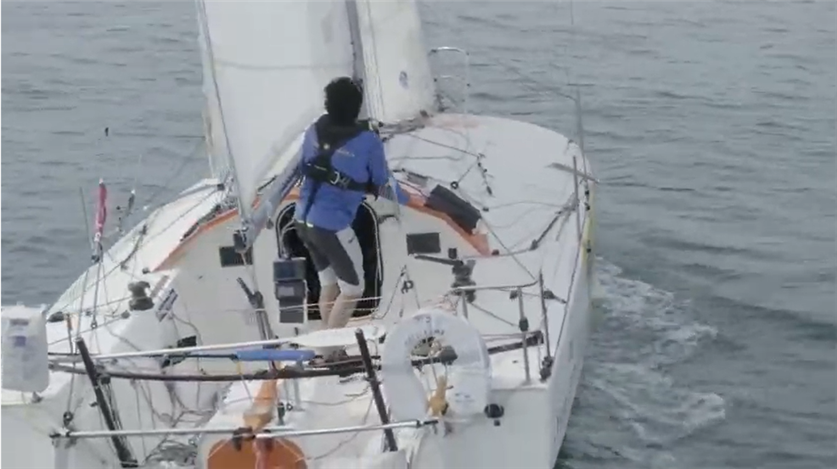
In light of all the characteristics that distinguish this challenge, such as passion, determination, performance, resilience and technology, Farnell decided to partner with Alberto and help him by opening the project up to our open-source design community to redesign his autopilot. As technologies develop further and faster, we are confident that our electronics enthusiasts could highly improve it to achieve higher performances with better cost efficiency.
image

Among the improvements Alberto would add, he would certainly focus on changing the current screen (which was an additional cost on the overall system) in favour of taking advantage of new smart phone technologies. Connecting a smart phone to the automatic navigation system could allow to cut a big part of development and budget effort, as it would allow to use the embedded characteristics of modern displays such as waterproofness and mechanical resistance, and make it further flexible and efficient.

Join Alberto in his challenge!

Auto Pilot Components

What do you need for a boat to sail its self? 

The autopilot is made by two parts: The data acquisition and the control part.
Several sensor are connected to the system to perform the vectorial calculation of the wind and gain information about the heading of the boat: IMU compass, wind sensor, boat speed sensor and a rudder sensor.

The calculated variables are used to keep the boat on a particular true wind angle or on a particular course. Two nested PID controllers allow the boat to keep the desired route moving the rudder through a linear actuator.

The first PID calculates the desired rudder angle. The second PID, thanks to the rudder angle sensor feedback, drives the motor of the actuator to the desired rudder angle.

The first controller can be set to follow a particular reference: TWA (True Wind Angle), AWA (Apparent Wind Angle), Internal Gyro Compass (preferred choice), Fixed Rudder Angle (debugging purpose).


Ancient mariners would tie the rudder with a rope but this could run them into rocks in their sleep. 
Alberto has used electronics to monitor the wind, position and control it all with an Arduino 

image

Components 

Learn more about the components used in this build

image image image image image
Arduino Max232 Driver Interface 12v-5v DC to DC Converter H-Bridge Motor Drivers Resistors 

Arduino

Driver Interfaces DC to DC Converters Motor Drivers Resistors

Are you ready for Tomorrow? 

Competition

Global Competition
Winner
riky_electronicmarine 
Australia and New Zealand
Winner
Gough Lui 

India
Winner
rsjawale24 

Greater China
(China, Taiwan, Hong Kong)
Closed

ASEAN
(Singapore, Malaysia, Phillipines, Vietnam, Thailand) + Korea

Winner
abyraj 
image image image image image


Enter our "Ready for Tomorrow" competition for a chance to win a prize from our prize pool

Multicomp Pro Handheld Oscilloscope - Hand Held Oscilloscope
Multicomp Pro PC USB Oscilloscope - USB Oscilloscope
Multicomp Pro Soldering Station - Soldering Station

Mulitcomp Pro Handheld Multimeter - Multimeter


Details of your answers and contact details can be shared with element14 Avnet Group


  • ReadyForTomorrow
  • Share
  • History
  • More
  • Cancel
  • Sign in to reply

Top Comments

  • e14phil
    e14phil over 2 years ago +2
    Congratulation to the Winners of the following Challenges: Global Competition Winner - Will win the full Global Competition Prize pool riky_electronicmarine Australia and New Zealand Winner - Will win…
  • riky_electronicmarine
    riky_electronicmarine over 3 years ago +1
    ok who won the prises?
  • rsjawale24
    rsjawale24 over 2 years ago in reply to dougw +1
    Thanks! Really excited to see what prize do I get from the pool! A handheld oscilloscope would be nice as I don't have a scope with a screen yet..I just received my USB scope as project14 prize
Parents
  • riky_electronicmarine
    riky_electronicmarine over 3 years ago

    Who m I: a nerd with passion in sailing that fixes marine electronics reverse engineering most of them since schematics are not available. Electronicmarine on youtube.

    Premises: An autopilot system used on a mini, especially when solo sailing must fulfill a serries of requirements:

    TO BE RELIABLE FIRST OF ALL!!! (an unwanted chinese jibe when you are on the deck can kill you in the middle of the ocean)

    To draw less power possible, since the amount of energy onboard is really limited

    To be able to steer the boat under heavy wind and sea conditions

    Last but not list: to keep the boat fast under all range of wind and sea- after all is a race!

    Start with the basics: how an autopilot for a boat work: the compass module (sometimes called fluxgate) take a reading, compare it with a set course, then command the actuator to move the helm to try to reach that bearing, the helm angle is read by a rudder reference sensor to know how much it moves then corrects until the desidered course is reached (in theory) in practice things complicate a lot more (maybe will go back to this argument later- ask me how I know :) ).

    The second operation mode desired on a mini is have it operate on the TWA (true wind angle), and here the things complicate a lot more, first of all you need an acurate wind sensor with dedicated wind speed data and wind angle data, fast data, possibly with the posibility to change the damping and averaging of readings depending on wind and sea conditions. Altough is feaseble to buid one, it's much simpler to get an already made solution on the market since the adc converssions, callibrations, various options in dealing and processing all that part will take a lot of space and processor working time and just makes debughing and proggraming a lot more difficult and it requires aeither a separate processor or a multitasking real time one that is not easy to proggram by an average arduino user. After having a relible wind data, it needs a mems packege (gyro and accelometers) barometric pressure or water temperature, or air temperature not really needed since is not a NASA prodgect who take in consideration all those variables, Focus on the important things first. Having solved the reading of the mems packege and sucessfully implemented a kalmann filter the rest of the math can be solved knowing the mast height (they are in class requirements) and calculating the position of the mems location from the center of rotation of the boat you can then calculate the TWA and TWS when the boat gets leaned and throwed away by the waves.

    Having solved that part the rest can be easy (or at list is seems) moving an actuator motor and get back the feedback from a rudder sensor.

    The rudder sensor used by a lot of manufacturers is relativeley simple, I can even 3dprint them, one potentiometer enclosed in a waterthight enclosure, they use quality vishay or burns industrial potentiometers with values between 2.5 and 5k.

    The actuator arm and system is what stayed behind in the past 30 years, there ater basically 2 systems: one linear ballscew type and one with an electric reversible hydraulic pump that moves a piston, (raymarine t1/st4000 tiller and the second type lecomble&scmidt or the ramdrive from b&g are the most used on mini) but both have one base problem: ineficiency in transforming the energy into movment due to the classical brushed motors used inside. In the past 15 years they have tried to minimise the power draw by using pwm to controll a soft start and operation of the dc motros.

    PROBLEM WITH ALMOST ALL AMATEUR BUILD AUTOPILOTS (and some commercial ones also): most of them do not incorporate a monitoring system for what is the power draw of the motor and do not incorporate protections for motor unwanted stall or if is forced, this blow up the mosfets in the H brige!!!! so in order to have a certain reliabilty on the system a somekind of amperometric protection must be designed from the beginning, it might seem easy to implement but since is pwm controlled it can be a challenge for an untried eye (just the timing of the reading and interrupt routines can be a bit tricky). For that purpouse the hall sensors that are prone to interferrences do not work well in this kind of the applications and a shunt solution is much preffered.

    Since i've mentioned the interferrences, most hobysts just think that the power in a boat is clean as in a lab, definetley not true, hence all analog imputs must be properly filtered and protected against spikes, ripples and other type of interferences present onboard, agaian ask me how I know :) The adc pins that read the rudder sensor for instance and adc reffrece voltage on 5v microcontrollers for example is a lot better to be used on a 2.54v reffrence source, diode clamped externaly and pass thru resistor divider and then again a protection fast zener used... inductance filters also welcome on those inputs :)

    Now building it for the cheap on the hardware side is relatively easy, the part that is the most expensive is proggramming and debbughing...

    here you have 2 options: go with a lot of power like using a PI, or break the system in multiple microcontrollers and designate and optimise speciffic tasks with interrupt driven routines in order of importance and needs.

    I2c communications for amateur level in this kind of projects is better to let them aside if you are not custom build the pcb and take care in path design, altoug a lot of times they work, or seem to work, in alt more cases make bad jokes, intermitent failures that make debugghing a nightmare or induce catastrofical failures on the micro side...

    power filtering is a really important aspect also, automotive grade components are recomanded in this cases- cheap from car junkyard, a bit difficult to desolder but not that hard.

    Now for the display part: thiese days everybody wants nice colors led displays that have inside powerfull drivers and display nice grphics, the problem is that they consume too much power, so you can use one for debughing purpouses while you are building the system, but for the race time a ultra low power display with efficient back lightning is most recomanded.

    Since i've mentioned the low power: the micro-controllers you use should be possibly selected in the nanowatt family or a real ultra low power microcontrollers, the sleep routines should be used and wake up interrupts on speciffic events since you don't need it to run all the times...

    lLEARN FROM MY MISTAKES:

    do not use an H bridge Ic, have it custom build with discrete power mosfets and have in place an amperometric protection that autoresets itself.

    Use optocouplers between the micro-controller and power electronics, less magic smoke will be released :)

    properly filter the power parts and separate the power rails

    then everything else can be at later date integrated with an Bluetooth or wifi module in order to be send on some phone or tablet, although the class limitations do not allow them.

    At this point a way to easy remotely program the logic with a laptop can be maybe a lot more useful feature instead of inserting usb or ICSP

    • Cancel
    • Vote Up 0 Vote Down
    • Sign in to reply
    • More
    • Cancel
Comment
  • riky_electronicmarine
    riky_electronicmarine over 3 years ago

    Who m I: a nerd with passion in sailing that fixes marine electronics reverse engineering most of them since schematics are not available. Electronicmarine on youtube.

    Premises: An autopilot system used on a mini, especially when solo sailing must fulfill a serries of requirements:

    TO BE RELIABLE FIRST OF ALL!!! (an unwanted chinese jibe when you are on the deck can kill you in the middle of the ocean)

    To draw less power possible, since the amount of energy onboard is really limited

    To be able to steer the boat under heavy wind and sea conditions

    Last but not list: to keep the boat fast under all range of wind and sea- after all is a race!

    Start with the basics: how an autopilot for a boat work: the compass module (sometimes called fluxgate) take a reading, compare it with a set course, then command the actuator to move the helm to try to reach that bearing, the helm angle is read by a rudder reference sensor to know how much it moves then corrects until the desidered course is reached (in theory) in practice things complicate a lot more (maybe will go back to this argument later- ask me how I know :) ).

    The second operation mode desired on a mini is have it operate on the TWA (true wind angle), and here the things complicate a lot more, first of all you need an acurate wind sensor with dedicated wind speed data and wind angle data, fast data, possibly with the posibility to change the damping and averaging of readings depending on wind and sea conditions. Altough is feaseble to buid one, it's much simpler to get an already made solution on the market since the adc converssions, callibrations, various options in dealing and processing all that part will take a lot of space and processor working time and just makes debughing and proggraming a lot more difficult and it requires aeither a separate processor or a multitasking real time one that is not easy to proggram by an average arduino user. After having a relible wind data, it needs a mems packege (gyro and accelometers) barometric pressure or water temperature, or air temperature not really needed since is not a NASA prodgect who take in consideration all those variables, Focus on the important things first. Having solved the reading of the mems packege and sucessfully implemented a kalmann filter the rest of the math can be solved knowing the mast height (they are in class requirements) and calculating the position of the mems location from the center of rotation of the boat you can then calculate the TWA and TWS when the boat gets leaned and throwed away by the waves.

    Having solved that part the rest can be easy (or at list is seems) moving an actuator motor and get back the feedback from a rudder sensor.

    The rudder sensor used by a lot of manufacturers is relativeley simple, I can even 3dprint them, one potentiometer enclosed in a waterthight enclosure, they use quality vishay or burns industrial potentiometers with values between 2.5 and 5k.

    The actuator arm and system is what stayed behind in the past 30 years, there ater basically 2 systems: one linear ballscew type and one with an electric reversible hydraulic pump that moves a piston, (raymarine t1/st4000 tiller and the second type lecomble&scmidt or the ramdrive from b&g are the most used on mini) but both have one base problem: ineficiency in transforming the energy into movment due to the classical brushed motors used inside. In the past 15 years they have tried to minimise the power draw by using pwm to controll a soft start and operation of the dc motros.

    PROBLEM WITH ALMOST ALL AMATEUR BUILD AUTOPILOTS (and some commercial ones also): most of them do not incorporate a monitoring system for what is the power draw of the motor and do not incorporate protections for motor unwanted stall or if is forced, this blow up the mosfets in the H brige!!!! so in order to have a certain reliabilty on the system a somekind of amperometric protection must be designed from the beginning, it might seem easy to implement but since is pwm controlled it can be a challenge for an untried eye (just the timing of the reading and interrupt routines can be a bit tricky). For that purpouse the hall sensors that are prone to interferrences do not work well in this kind of the applications and a shunt solution is much preffered.

    Since i've mentioned the interferrences, most hobysts just think that the power in a boat is clean as in a lab, definetley not true, hence all analog imputs must be properly filtered and protected against spikes, ripples and other type of interferences present onboard, agaian ask me how I know :) The adc pins that read the rudder sensor for instance and adc reffrece voltage on 5v microcontrollers for example is a lot better to be used on a 2.54v reffrence source, diode clamped externaly and pass thru resistor divider and then again a protection fast zener used... inductance filters also welcome on those inputs :)

    Now building it for the cheap on the hardware side is relatively easy, the part that is the most expensive is proggramming and debbughing...

    here you have 2 options: go with a lot of power like using a PI, or break the system in multiple microcontrollers and designate and optimise speciffic tasks with interrupt driven routines in order of importance and needs.

    I2c communications for amateur level in this kind of projects is better to let them aside if you are not custom build the pcb and take care in path design, altoug a lot of times they work, or seem to work, in alt more cases make bad jokes, intermitent failures that make debugghing a nightmare or induce catastrofical failures on the micro side...

    power filtering is a really important aspect also, automotive grade components are recomanded in this cases- cheap from car junkyard, a bit difficult to desolder but not that hard.

    Now for the display part: thiese days everybody wants nice colors led displays that have inside powerfull drivers and display nice grphics, the problem is that they consume too much power, so you can use one for debughing purpouses while you are building the system, but for the race time a ultra low power display with efficient back lightning is most recomanded.

    Since i've mentioned the low power: the micro-controllers you use should be possibly selected in the nanowatt family or a real ultra low power microcontrollers, the sleep routines should be used and wake up interrupts on speciffic events since you don't need it to run all the times...

    lLEARN FROM MY MISTAKES:

    do not use an H bridge Ic, have it custom build with discrete power mosfets and have in place an amperometric protection that autoresets itself.

    Use optocouplers between the micro-controller and power electronics, less magic smoke will be released :)

    properly filter the power parts and separate the power rails

    then everything else can be at later date integrated with an Bluetooth or wifi module in order to be send on some phone or tablet, although the class limitations do not allow them.

    At this point a way to easy remotely program the logic with a laptop can be maybe a lot more useful feature instead of inserting usb or ICSP

    • Cancel
    • Vote Up 0 Vote Down
    • Sign in to reply
    • More
    • Cancel
Children
  • riky_electronicmarine
    riky_electronicmarine over 3 years ago in reply to riky_electronicmarine

    Now broken into pieces and maybe with the comunity help maybe wee can really buid a working cheap syetem, the wind part for the mechanics 3dprinted, rudder sensor and power filtering parts can be build easy... the hardware design and phisically build is easy to me also to do in really fast timeframe since i stihave all my protoiping tools in house... the proggraming and debughing time is the one i don't have...

    • Cancel
    • Vote Up 0 Vote Down
    • Sign in to reply
    • More
    • Cancel
  • e14phil
    e14phil over 2 years ago in reply to riky_electronicmarine

    Congratulations riky_electronicmarine This comment is the winning comment! I have sent you a message regards your prizes!

    • Cancel
    • Vote Up 0 Vote Down
    • Sign in to reply
    • More
    • Cancel
element14 Community

element14 is the first online community specifically for engineers. Connect with your peers and get expert answers to your questions.

  • Members
  • Learn
  • Technologies
  • Challenges & Projects
  • Products
  • Store
  • About Us
  • Feedback & Support
  • FAQs
  • Terms of Use
  • Privacy Policy
  • Legal and Copyright Notices
  • Sitemap
  • Cookies

An Avnet Company © 2025 Premier Farnell Limited. All Rights Reserved.

Premier Farnell Ltd, registered in England and Wales (no 00876412), registered office: Farnell House, Forge Lane, Leeds LS12 2NE.

ICP 备案号 10220084.

Follow element14

  • X
  • Facebook
  • linkedin
  • YouTube