element14 Community
element14 Community
    Register Log In
  • Site
  • Search
  • Log In Register
  • Community Hub
    Community Hub
    • What's New on element14
    • Feedback and Support
    • Benefits of Membership
    • Personal Blogs
    • Members Area
    • Achievement Levels
  • Learn
    Learn
    • Ask an Expert
    • eBooks
    • element14 presents
    • Learning Center
    • Tech Spotlight
    • STEM Academy
    • Webinars, Training and Events
    • Learning Groups
  • Technologies
    Technologies
    • 3D Printing
    • FPGA
    • Industrial Automation
    • Internet of Things
    • Power & Energy
    • Sensors
    • Technology Groups
  • Challenges & Projects
    Challenges & Projects
    • Design Challenges
    • element14 presents Projects
    • Project14
    • Arduino Projects
    • Raspberry Pi Projects
    • Project Groups
  • Products
    Products
    • Arduino
    • Avnet & Tria Boards Community
    • Dev Tools
    • Manufacturers
    • Multicomp Pro
    • Product Groups
    • Raspberry Pi
    • RoadTests & Reviews
  • About Us
    About the element14 Community
  • Store
    Store
    • Visit Your Store
    • Choose another store...
      • Europe
      •  Austria (German)
      •  Belgium (Dutch, French)
      •  Bulgaria (Bulgarian)
      •  Czech Republic (Czech)
      •  Denmark (Danish)
      •  Estonia (Estonian)
      •  Finland (Finnish)
      •  France (French)
      •  Germany (German)
      •  Hungary (Hungarian)
      •  Ireland
      •  Israel
      •  Italy (Italian)
      •  Latvia (Latvian)
      •  
      •  Lithuania (Lithuanian)
      •  Netherlands (Dutch)
      •  Norway (Norwegian)
      •  Poland (Polish)
      •  Portugal (Portuguese)
      •  Romania (Romanian)
      •  Russia (Russian)
      •  Slovakia (Slovak)
      •  Slovenia (Slovenian)
      •  Spain (Spanish)
      •  Sweden (Swedish)
      •  Switzerland(German, French)
      •  Turkey (Turkish)
      •  United Kingdom
      • Asia Pacific
      •  Australia
      •  China
      •  Hong Kong
      •  India
      •  Japan
      •  Korea (Korean)
      •  Malaysia
      •  New Zealand
      •  Philippines
      •  Singapore
      •  Taiwan
      •  Thailand (Thai)
      •  Vietnam
      • Americas
      •  Brazil (Portuguese)
      •  Canada
      •  Mexico (Spanish)
      •  United States
      Can't find the country/region you're looking for? Visit our export site or find a local distributor.
  • Translate
  • Profile
  • Settings
Internet of Things
  • Technologies
  • More
Internet of Things
Documents Sailing Auto Pilot - Competition - Ready For Tomorrow 2022
  • Blog
  • Forum
  • Documents
  • Quiz
  • Events
  • Polls
  • Members
  • Mentions
  • Sub-Groups
  • Tags
  • More
  • Cancel
  • New
Join Internet of Things to participate - click to join for free!
Actions
  • Share
  • More
  • Cancel
Engagement
  • Author Author: e14phil
  • Date Created: 28 Feb 2022 8:57 AM Date Created
  • Last Updated Last Updated: 29 Nov 2022 2:03 PM
  • Views 17427 views
  • Likes 16 likes
  • Comments 61 comments
Related
Recommended

Sailing Auto Pilot - Competition - Ready For Tomorrow 2022

Farnell partners with sailor Alberto Riva to redevelop a Nautical Autopilot image

Alberto Riva is a multi-competition winning skipper who always had a passion for sailing since he was a child.

With the support of many different sponsors, he has sailed on a variety of boats from smaller centreboard boats to 70ft long flying trimarans, on board of which he competed many different regattas.i

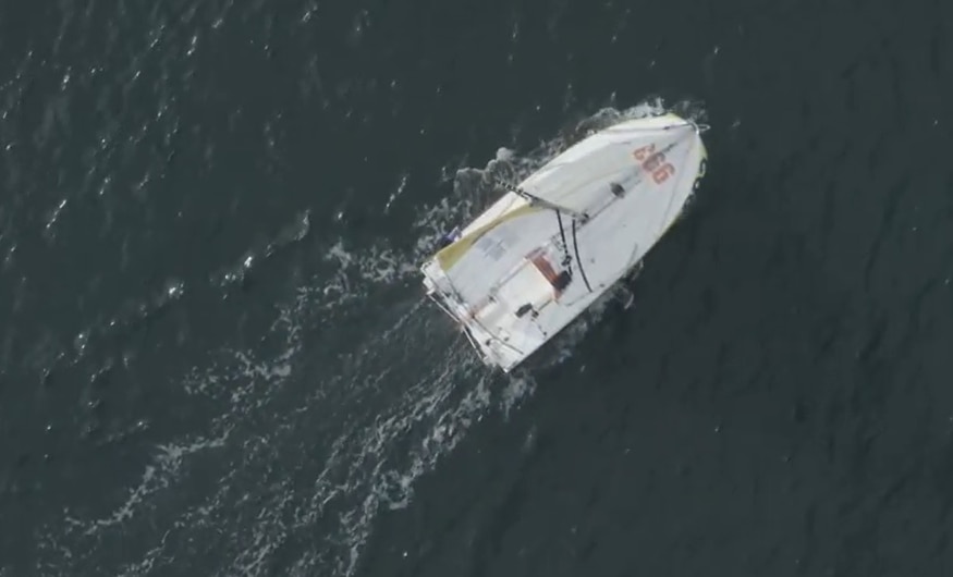
He now has an eye on a new dream: the Mini Transat - a 4050 nautical miles solo race on the smallest offshore racing boats at only 6.50m long. A challenge that requires not only competence and resilience, but also a sound mind.

You don't have permission to edit metadata of this video.
Edit media
x
image
Upload Preview
image

Far from being only a sailing passionate and competitor, indeed, Alberto is also a trained engineer who worked as data analyst and on-board electronics expert for the preparation of other racing boats. With a master in nanotechnologies, he also developed an auto-pilot board during his studies

.image

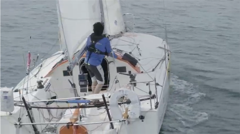
The auto-pilot is an element that he defines “his best friend” during sailing, as it allows him to leave the wheel and rest or focus on weather conditions especially on demanding regattas like the Transat, where one-person sailing and no phone/computer or technical support aside from tracking are the main requirements.

image

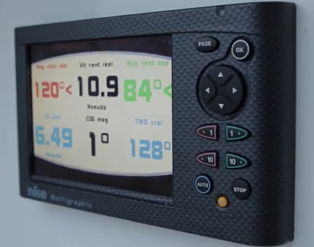
Interface for AutoPilot 

In light of all the characteristics that distinguish this challenge, such as passion, determination, performance, resilience and technology, Farnell decided to partner with Alberto and help him by opening the project up to our open-source design community to redesign his autopilot. As technologies develop further and faster, we are confident that our electronics enthusiasts could highly improve it to achieve higher performances with better cost efficiency.

image

Among the improvements Alberto would add, he would certainly focus on changing the current screen (which was an additional cost on the overall system) in favour of taking advantage of new smart phone technologies. Connecting a smart phone to the automatic navigation system could allow to cut a big part of development and budget effort, as it would allow to use the embedded characteristics of modern displays such as waterproofness and mechanical resistance, and make it further flexible and efficient.

Join Alberto in his challenge!

Auto Pilot Components

What do you need for a boat to sail its self? 

The autopilot is made by two parts: The data acquisition and the control part.
Several sensor are connected to the system to perform the vectorial calculation of the wind and gain information about the heading of the boat: IMU compass, wind sensor, boat speed sensor and a rudder sensor.

The calculated variables are used to keep the boat on a particular true wind angle or on a particular course. Two nested PID controllers allow the boat to keep the desired route moving the rudder through a linear actuator.

The first PID calculates the desired rudder angle. The second PID, thanks to the rudder angle sensor feedback, drives the motor of the actuator to the desired rudder angle.

The first controller can be set to follow a particular reference: TWA (True Wind Angle), AWA (Apparent Wind Angle), Internal Gyro Compass (preferred choice), Fixed Rudder Angle (debugging purpose).


Ancient mariners would tie the rudder with a rope but this could run them into rocks in their sleep. 
Alberto has used electronics to monitor the wind, position and control it all with an Arduino 

image

Components 

Learn more about the components used in this build

image image image image image
Arduino Max232 Driver Interface 12v-5v DC to DC Converter H-Bridge Motor Drivers Resistors 

Arduino

Driver Interfaces DC to DC Converters Motor Drivers Resistors

Are you ready for Tomorrow? 

Competition

Global Competition
Winner
riky_electronicmarine 
Australia and New Zealand
Winner
Gough Lui 

India
Winner
rsjawale24 

Greater China
(China, Taiwan, Hong Kong)
Closed

ASEAN
(Singapore, Malaysia, Phillipines, Vietnam, Thailand) + Korea

Winner
abyraj 
image image image image image


Enter our "Ready for Tomorrow" competition for a chance to win a prize from our prize pool

Multicomp Pro Handheld Oscilloscope - Hand Held Oscilloscope
Multicomp Pro PC USB Oscilloscope - USB Oscilloscope
Multicomp Pro Soldering Station - Soldering Station

Mulitcomp Pro Handheld Multimeter - Multimeter


Details of your answers and contact details can be shared with element14 Avnet Group


  • ReadyForTomorrow
  • Share
  • History
  • More
  • Cancel
  • Sign in to reply

Top Comments

  • e14phil
    e14phil over 3 years ago +2
    Congratulation to the Winners of the following Challenges: Global Competition Winner - Will win the full Global Competition Prize pool riky_electronicmarine Australia and New Zealand Winner - Will win…
  • riky_electronicmarine
    riky_electronicmarine over 3 years ago +1
    ok who won the prises?
  • rsjawale24
    rsjawale24 over 3 years ago in reply to dougw +1
    Thanks! Really excited to see what prize do I get from the pool! A handheld oscilloscope would be nice as I don't have a scope with a screen yet..I just received my USB scope as project14 prize
  • riky_electronicmarine
    riky_electronicmarine over 3 years ago

    ok who won the prises?

    • Cancel
    • Vote Up +1 Vote Down
    • Sign in to reply
    • More
    • Cancel
  • ajayvishaal
    ajayvishaal over 3 years ago

    I've already worked on ROVs and UUVs. Since this is not an under water vehicle, I've some suggestions that can be added to the existing design. So the first thing is to integrate an SBC like Nvidia Jetson Nano or Raspberry Pi. This will add good computation power to the robot. Then coming to the software architecture, my suggestion is to deploy ROS on SBC. Since I'm a ROS Engineer curently working on Autonomous UUVs, I've seen in real time that ROS is robust for making this kind of system into an intelligent machine in a cost effective manner. And next thing is sensor fusion, since the robot moves on the surface of water, we don't need to wory about buoyancy control things. So we can easily focus on sensor fusion part. For that we need an IMU sensor and GPS module and using filters like EKF we can fuse the sensor data to get the accurate pose of the drone. When coming to the obstacle detection part, we can go with 2 sensors. One is Lidars, to detect the obstacles like another boat near by the robot or some other obstacle over the surface of sea. And another one is sonars, which can be mounted under the robot to detect obsacles that is below the surface of water. So Inorder to make the system to avoid obstacles we are going to utilize the Lidar and sonar sensor and control the thruster and rudder of the bot. As far as I understand, It seems like arduino is used for controlling the actuators. So we can utilize the ROSserial communication protocol to make the SBC to talk to the Arduino. So we need to create a script by utilizing the lidar and sonar data and then make the actuators move accordingly based on the obstacle detection.Now coming to the autonomous part, we can use GPS waypoint based navigation by integrating all the features that I've mentioned previously. By this way, the system will be more robust and at the same time will be intelligent. And my final suggestion is creating a custom dashboard, with speedometer dial, battery level indicator, compass and orientaion dials. This makes the user to understand about the bot's current heading direction and all other essential informations. Hope my suggestions helps to develop the robot into a better and intelligent one.

    • Cancel
    • Vote Up 0 Vote Down
    • Sign in to reply
    • More
    • Cancel
  • Visionslab
    Visionslab over 3 years ago

    A thing about the display. You should be able to read this in full sunlight. On plotters for navigation they use 500+nits color screens. Those are expensive and power hungry. You could use a waterproof e-reader like the kobo h2o. It is water proof and has a good screen, backlight and wifi. It saves you from having to build a waterproof case. You can probably get one cheap second hand.  

    • Cancel
    • Vote Up 0 Vote Down
    • Sign in to reply
    • More
    • Cancel
  • rsjawale24
    rsjawale24 over 3 years ago

    I think while suggesting many advanced auto-pilot system details, we all forgot the main thing in an auto-pilot system... the manual override switch. Just in case the control has to be transferred to the user, if the autopilot system fails or otherwise. 

    • Cancel
    • Vote Up 0 Vote Down
    • Sign in to reply
    • More
    • Cancel
  • amgalbu
    amgalbu over 3 years ago

    Another suggestion to improve the autopilot. I would add a strain sensor on the mainsail as shown in picture

    image

    The autopilot will read the force "exerted" by the mainsail. A drop or change in the detected strain means that the sail is flapping due the the wind flow starting to detach from the sail surface. This can trigger some corrections from autopilot to get back to the optimal course. When the sailor sets an heading on the autopilot, the autopilot itself will read the current force detected by the strain sensor and will continuously try to keep this level of force by slightly correcting the course. A proper algorithm needs to be implemented to prevent an excessive drift from the desired heading  

    Here are some examples of how the autopilot can leverage the feedback provided by the strain sensor

    1. prevent the mainsail from crossing the boat in case of sudden changes in wind direction. This safety function could be automatically disabled by some switches on the helm that detect that the maneuver has been intentionally initiated by the sailor
      image
    2. prevent damages due to strong wind: when detected forces raise above a safety threshold, the autopilot could correct the course to go closer to the eye of the wind, thus reducing the stress on the sails
    3. when sailing closed-hauled, correct the course to make the boat stay on the "sweetspot" on the border of the "no-go zone". More precisely, when the sail starts flapping, the strain sensor will detect a drop in force exerted by the sail and will correct the course to go automatically closer to the wind
    • Cancel
    • Vote Up 0 Vote Down
    • Sign in to reply
    • More
    • Cancel
  • jft07
    jft07 over 3 years ago

    Very nice project !
    It's funny, we are working on a somewhat similar project with a sailor who has done the Mini-Transat 6.50 (Edwin on the mini 6.50 Nacira "Coeur Fidele", 7th production boat in 2015)
    We are developing an autopilot mainly based on the raspberry Pi4, open source, and maybe we could suggest some ideas...
    Some info here (not really up-to-date):
    https://sailing.netcys.com/
    The autopilot must support different algorithms, from the simple PID to more advanced solutions : we are testing solutions using "auto learning" from monitored information from sensors (wind, heel, speed, ...) and computing power of Pi4 is really required ...


    Another idea for Alberto's project:
    something very useful for solo sailing, inexpensive, and easy to build, is a voice alarm reporting system that monitors NMEA status. Alberto's boat is equipped with NKE electronics, and the easiest way is to use the Topline-NMEA output option.
    The “voice synthesis alarm reporting system” assists the skipper to monitor the main parameters available on the boat, from the different sensors: wind, depth, loch, …
    Alarm messages are played on the Audio output to be mixed with the audio output of the on-board VHF, and to be transmitted to the cockpit speaker.
    For example, a significant change in wind angle, or wind speed, etc. generates a detailed voice alarm, which allows the skipper to take better advantage of short periods of solo sailing rest ...
    We had made this simple piece of equipment with a Raspberry Pi3, and with a very inexpensive little color screen for the Raspberry for the Mini Transat 2015 ...
    When solo sailing, voice synthesis alarm may be more useful than a simple sound alarm ...

    • Cancel
    • Vote Up 0 Vote Down
    • Sign in to reply
    • More
    • Cancel
  • raffi3438
    raffi3438 over 3 years ago

    Because the autopilot is not allowed to change the sail trim, it could change the direction to optimize the sail trim.

    Thanks to a digital telltale, the autopilot will be able to know the efficiency of the sail trim in relation to the direction.
    If the wind turns, and the direction is more favorable, then the autopilot will change the helm in that direction.

    Technically, a digital telltale would be composed of 2 telltales (a piece of fabric), one on each side of the sail.
    Each telltale is composed of a Bluetooth Low Energer (BLE) transmitter and a gyroscope at its end. The autopilot has basically to compare the tilt of the 2 telltales (thanks to the data of the gyroscopes transmitted in BLE) in order to know if the sail trim is optimized and if not it will also know in which direction to go to optimize it.

    Passionate about sailing and embedded development, I will develop this project in open source with great pleasure!

    • Cancel
    • Vote Up 0 Vote Down
    • Sign in to reply
    • More
    • Cancel
  • rsjawale24
    rsjawale24 over 3 years ago in reply to Visionslab

    Good suggestions for the auto pilot system however, GPS is not allowed as per the rules

    • Cancel
    • Vote Up 0 Vote Down
    • Sign in to reply
    • More
    • Cancel
  • amgalbu
    amgalbu over 3 years ago in reply to rsjawale24

    Hi rsjawale24. Thanks for your comment. Since Alberto was going to user a smartphone to remotely control the autopilot, I thought to exploit the same wireless communication channel (I proposed BLE, but wifi is fine too) to send route adjustment commands. I don't think this is a safety-critical application: this is just a "gadget" to make sailing more efficient by letting the sailor react faster to changes in wind direction. If a gesture is not detected or there are delays in communication, the boat will simply maintain the current route and the worst that can happen is that you have to reach the autopilot and change the course using the local commands. On the contrary, a wireless man overboard device is a safety-critical device and, as, such, should be properly engineered and validated. Finally, I proposed gestures because a gesture requires just one hand. This means, for example, that you can change course while operating a winch

    • Cancel
    • Vote Up 0 Vote Down
    • Sign in to reply
    • More
    • Cancel
  • Visionslab
    Visionslab over 3 years ago

    Also, in a system like this it is nice to keep things modular. So you have the ability to replace parts. Things break or get wet and burn out. Once on my autopilot the drive transistors did burn out on my Raymarine autohelm. Luckily I had an old one laying around and could desolder the transistors of that one. It was no race so I had time. But things break when you push them to the limit, and then having a spare is nice.

    As in system stability it could be a good idea to run this on a dedicated mcu. Then you have complete control, development time will increase thou. Systems like this should be very stable. 

    Also in this race electronic map software is forbidden. If you run a system that could use an electronic map, like OpenCPN but does not because it is against the rules. The jury could rule against allowing the system because you could install it easy even when you are underway. If the mcu does not run linux, openCPN would be impossible. 

    Linking the system to a vhf is not allowed but there is a transponder to keep track of the ships. You maybe could hook into this system in case of an emergency. Later when the race is finished you can upgrade the system to include the vhf and ais.

    As for the practical side. It is a small boat so I guess the lineair drive is not so very power hungry. (Blowing out the transistors of the Autohelm was on a 22ft sailing boat, so about the same size). To keep things modular and linux free the arduino shields could work: the A000079 motor driver with 4A drive capacity. A GPS like the MIKROE-1714 and a IMU like the MIKROE-1577 and 10212635-00 for weather sensing. Your boat has a wind vane and wind speed sensor, those work with NMEA2000 if it is a modern sensor, for this you will need a CAN shield:MIKROE-4107.

    As for the MCU go or something like the H7 lots of space speed and connectivity. 

    As for the rest of the electronics you can put it on a base board where you can connect all the modules together. If something breaks just replace the module.

    • Cancel
    • Vote Up 0 Vote Down
    • Sign in to reply
    • More
    • Cancel
<>
element14 Community

element14 is the first online community specifically for engineers. Connect with your peers and get expert answers to your questions.

  • Members
  • Learn
  • Technologies
  • Challenges & Projects
  • Products
  • Store
  • About Us
  • Feedback & Support
  • FAQs
  • Terms of Use
  • Privacy Policy
  • Legal and Copyright Notices
  • Sitemap
  • Cookies

An Avnet Company © 2026 Premier Farnell Limited. All Rights Reserved.

Premier Farnell Ltd, registered in England and Wales (no 00876412), registered office: Farnell House, Forge Lane, Leeds LS12 2NE.

ICP 备案号 10220084.

Follow element14

  • X
  • Facebook
  • linkedin
  • YouTube