element14 Community
element14 Community
    Register Log In
  • Site
  • Search
  • Log In Register
  • Members
    Members
    • Achievement Levels
    • Benefits of Membership
    • Feedback and Support
    • Members Area
    • Personal Blogs
    • What's New on element14
  • Learn
    Learn
    • eBooks
    • Learning Center
    • Learning Groups
    • STEM Academy
    • Webinars, Training and Events
  • Technologies
    Technologies
    • 3D Printing
    • Experts & Guidance
    • FPGA
    • Industrial Automation
    • Internet of Things
    • Power & Energy
    • Sensors
    • Technology Groups
  • Challenges & Projects
    Challenges & Projects
    • Arduino Projects
    • Design Challenges
    • element14 presents
    • Project14
    • Project Groups
    • Raspberry Pi Projects
  • Products
    Products
    • Arduino
    • Avnet Boards Community
    • Dev Tools
    • Manufacturers
    • Product Groups
    • Raspberry Pi
    • RoadTests & Reviews
  • Store
    Store
    • Visit Your Store
    • Or choose another store...
      • Europe
      •  Austria (German)
      •  Belgium (Dutch, French)
      •  Bulgaria (Bulgarian)
      •  Czech Republic (Czech)
      •  Denmark (Danish)
      •  Estonia (Estonian)
      •  Finland (Finnish)
      •  France (French)
      •  Germany (German)
      •  Hungary (Hungarian)
      •  Ireland
      •  Israel
      •  Italy (Italian)
      •  Latvia (Latvian)
      •  
      •  Lithuania (Lithuanian)
      •  Netherlands (Dutch)
      •  Norway (Norwegian)
      •  Poland (Polish)
      •  Portugal (Portuguese)
      •  Romania (Romanian)
      •  Russia (Russian)
      •  Slovakia (Slovak)
      •  Slovenia (Slovenian)
      •  Spain (Spanish)
      •  Sweden (Swedish)
      •  Switzerland(German, French)
      •  Turkey (Turkish)
      •  United Kingdom
      • Asia Pacific
      •  Australia
      •  China
      •  Hong Kong
      •  India
      •  Korea (Korean)
      •  Malaysia
      •  New Zealand
      •  Philippines
      •  Singapore
      •  Taiwan
      •  Thailand (Thai)
      • Americas
      •  Brazil (Portuguese)
      •  Canada
      •  Mexico (Spanish)
      •  United States
      Can't find the country/region you're looking for? Visit our export site or find a local distributor.
  • Translate
  • Profile
Medical
  • Technologies
  • More
Medical
Blog Oxygen Saturation - SpO2 Measurement
  • Blog
  • Forum
  • Documents
  • Events
  • Polls
  • Members
  • Mentions
  • Sub-Groups
  • Tags
  • More
  • Cancel
  • New
Medical requires membership for participation - click to join
Blog Post Actions
  • Subscribe by email
  • More
  • Cancel
  • Share
  • Subscribe by email
  • More
  • Cancel
Group Actions
  • Group RSS
  • More
  • Cancel
Engagement
  • Author Author: aswinvenu
  • Date Created: 29 Jul 2020 5:27 PM Date Created
  • Views 1966 views
  • Likes 6 likes
  • Comments 2 comments
Related
Recommended

Oxygen Saturation - SpO2 Measurement

aswinvenu
aswinvenu
29 Jul 2020

In the recent past I have seen a lot of questions from fellow community members about how to calculate Oxygen Saturation- SpO2 using "Photoplethysmography" or PPG.

The World is going through a tough time and  lot of people are infact talking about the scope of home monitoring and remote monitoring.

In this blog post I would like to explain how SpO2 is calculated using a cheap PPG sensor.


The setup :

  • BeagleBoneBlack Rev 3 (https://beagleboard.org/black)
  • MAX30100 (https://www.maximintegrated.com/en/products/sensors/MAX30100.html)

image


MAX30100 is a PPG sensor manufactured by Maxim Integrated. The sensor features RED(660nm) and IR(880nm) LEDs , a photo detector  and a processing unit.


Photoplethysmography (PPG) is a simple optical technique used to detect volumetric changes in blood in peripheral circulation. It is a low cost and non-invasive method that makes measurements at the surface of the skin. (https://www.news-medical.net/health/Photoplethysmography-(PPG).aspx )


Photons will be emitted from one or multiple sources to the human tissue. (generally focusing to places where the concentration of arterioles are high. Like Finger tips and ear lobes) Light emitted will either get absorbed by the tissue or reflected back. This photons will be picked up by a set of photo detectors.


There are two main types sensors available

  • Reflective
  • Transmissive


MAX30100 is a reflective PPG sensor. Which means the light source and the light sensor lies in the same horizontal plane. The light emitted from the source get reflected from the target and monitors at the light sensor.


MAX30100 has an IIO driver available for linux(https://github.com/torvalds/linux/blob/master/drivers/iio/health/max30100.c ). This is the reason why I chose Beaglebone black as the processor board. So I wired up the max30100 to my BBB.

image


MAX30100 uses I2C bus and the module address is 0x57.

Beaglebone black has 3 I2C buses. Unfortunately I2C 0 (The one which is enabled by default )can't be used because an EEPROM with the same address is present at the board.


So enable the I2C1 and register max30100@57


&i2c1 {
        max30100@57 {
                reg = <0x57>;
                compatible = "maxim,max30100";

                pinctrl-names = "default";
                pinctrl-0 = <&max30100_pins>;

                maxim,led-current-microamp =
                        <24000>,  // max RGB led current in μA
                        <50000>;  // max IR led current in μA

                interrupts-extended = <&gpio1 28 IRQ_TYPE_EDGE_FALLING>;
        };
};


Write a device tree overlay and edit the /boot/uEnv.txt

uboot_overlay_addr4=/lib/firmware/i2c1-max30100.dtbo


After the reboot IIO device will appear. Confirm it by checking /sys/bus/iio/devices

two devices got listed one is the ADC which is a platform device enabled by default and the new max30100.

use lsmod command to confirm.

image


change the directory to iio:device1 and take a look at the internals

image

scan_elements will contain the channel enable, channel index and channel type

image

to enable both RED and IR channels write 1 to the "in_intensity_red_en" and "in_intensity_ir_en"

echo 1 > in_intensity_red_en
echo 1 > in_intensity_ir_en


MAX30100 uses triggered buffer method to access the data. Change the directory to buffers and enable the buffer

image

echo 1 > enable


Now the data will be streamed as a character device to the node created at /dev/iio:device1


read the data to a file.

cat iio:device1 > file.txt


This file can be processed in python.


MAX30100 provides 2 Bytes (unsigned 16 bit ) values of  RED and IR values. A parsing script has been written to analyze the data and calculate the SpO2


import matplotlib.pyplot as plt 
import numpy as np

import sys 

# Open the file
f = open(sys.argv[1], "rb")

# Global buffers for data
red = []
ir = []

while True:
        # reading 4 bytes
        temp = f.read(4)
        if temp != "" and len(temp) >= 4:
                # ir
                ir.append(temp[1] | (temp[0] << 8)) 
                # red
                red.append(temp[3] | (temp[2] << 8)) 
        else:
                break

# get the mean of the Red and IR
red_dc = np.mean(red[200:350])
ir_dc = np.mean(ir[200:350])

# get the ac content
red_ac = abs(max(red[200:350])-min(red[200:350]))
ir_ac = abs(max(ir[200:350])-min(ir[200:350]))

print("RED DC :{} IR DC :{}".format(red_dc, ir_dc))
print("RED AC :{} IR AC :{}".format(red_ac, ir_ac))

R = (red_ac/red_dc)/(ir_ac/ir_dc)
print("Factor R AC/DC red on AC/DC ir {}".format(R))
print("SpO2 :{}".format(110-25*R))

plt.plot(red[200:350])
plt.plot(ir[200:350])
plt.show()   


The sample plot are given below.

image

Both RED and IR signals have two parts an AC component and a DC component.


AC component represents the volumetric flow of blood.

DC component represents the reflected photos from the different tissue levels.


Now lets talk about SpO2

SpO2, also known as oxygen saturation, is a measure of the amount of oxygen-carrying hemoglobin in the blood relative to the amount of hemoglobin not carrying oxygen. (https://www.homecaremag.com/understanding-spo2-and-normal-oxygen-levels )


Oxyhemoglobin(HbO2)absorbs visible and infrared(IR) light differently than deoxyhemoglobin(Hb),and appears bright red as opposed to the darker brownHb. Absorption in the arterial blood is represented by an AC signal which is superimposed on a DC signal representing absorptions in other substances like pigmentation in tissue,venous,capillary,bone,and so forth. (https://www.ti.com/lit/an/slaa655/slaa655.pdf )

image


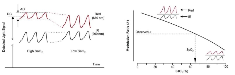
The SpO2 is the ratio of ratios AC over DC of RED and IR signals.


R = (AC of Red / DC of Red)/ (AC of IR / DC of IR


% SpO2 = 110 – 25 × R


image

Note : In the above code I have used maxima - minima to calculate the AC component. You can use RMS of the AC component to get slightly better results.

  • Sign in to reply

Top Comments

  • DAB
    DAB over 3 years ago +2
    Thanks for explaining how the ratios work. DAB
  • titusece
    titusece over 2 years ago

    Hello,


    Now the data will be streamed as a character device to the node created at /dev/iio:device1

    read the data to a file.

    1. cat iio:device1 > file.txt 


    I have enabled the MAX30102 sensor in same way, but streaming is not working.

    What is the wrong with my flow ?


    root@ninou-desktop:/sys/bus/iio/devices/iio:device1# cat in_temp_raw

    379

    root@ninou-desktop:/sys/bus/iio/devices/iio:device1# cat in_temp_scale

    0.062500000

    root@ninou-desktop:/sys/bus/iio/devices/iio:device1# cat buffer/enable

    1

    root@ninou-desktop:/sys/bus/iio/devices/iio:device1# cat scan_elements/in_intensity_ir_en

    1

    root@ninou-desktop:/sys/bus/iio/devices/iio:device1# cat scan_elements/in_intensity_red_en

    1

    root@ninou-desktop:/sys/bus/iio/devices/iio:device1#

    root@ninou-desktop:/sys/bus/iio/devices/iio:device1# cat scan_elements/in_intensity_red_index

    0

    root@ninou-desktop:/sys/bus/iio/devices/iio:device1# cat scan_elements/in_intensity_ir_index

    1

    root@ninou-desktop:/sys/bus/iio/devices/iio:device1#

    root@ninou-desktop:/sys/bus/iio/devices/iio:device1#

    root@ninou-desktop:/sys/bus/iio/devices/iio:device1# cat /dev/iio\:device1

    ^C --> I don't see any data here

    root@ninou-desktop:/sys/bus/iio/devices/iio:device1#


    root@ninou-desktop:/sys/bus/iio/devices/iio:device1# ls

    buffer  dev  in_temp_raw  in_temp_scale  name  of_node  power  scan_elements  subsystem  uevent

    root@ninou-desktop:/sys/bus/iio/devices/iio:device1# ls buffer/

    enable  length  watermark

    root@ninou-desktop:/sys/bus/iio/devices/iio:device1#

    • Cancel
    • Vote Up 0 Vote Down
    • Sign in to reply
    • More
    • Cancel
  • DAB
    DAB over 3 years ago

    Thanks for explaining how the ratios work.


    DAB

    • Cancel
    • Vote Up +2 Vote Down
    • Sign in to reply
    • More
    • Cancel
element14 Community

element14 is the first online community specifically for engineers. Connect with your peers and get expert answers to your questions.

  • Members
  • Learn
  • Technologies
  • Challenges & Projects
  • Products
  • Store
  • About Us
  • Feedback & Support
  • FAQs
  • Terms of Use
  • Privacy Policy
  • Legal and Copyright Notices
  • Sitemap
  • Cookies

An Avnet Company © 2023 Premier Farnell Limited. All Rights Reserved.

Premier Farnell Ltd, registered in England and Wales (no 00876412), registered office: Farnell House, Forge Lane, Leeds LS12 2NE.

ICP 备案号 10220084.

Follow element14

  • X
  • Facebook
  • linkedin
  • YouTube