The Face of each big industrial equipment is its control panel or face plate, however you would like to call it.
This entry of my CNC Blog will focus on that instead of making huge wiring progress, because I think it is:
A more interesting than you might think.
B better suited in my current time frame to do this task than cut hundreds of wires to length.
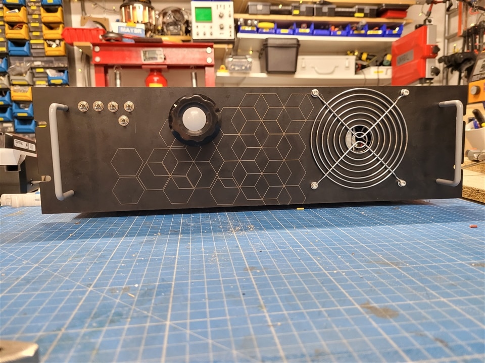
So the face plate of my CNC machine is identical to the front plate of the housing we mounted the Power supplies control board and motor drivers in the last Blog entry.
So you could say its an „All in one System“ apart from the actual machine movement controls being in a separate wireless entity that we build later on.
Requirements for the front plate are:
Mount for a potentiometer for manual spindle speed control
Switches to toggle, spindle, fans, pumps and lighting.
A hole just at the right position to allow airflow from one of the power supplies that happens to have a different fan orientation than the others.
And it should look cool.
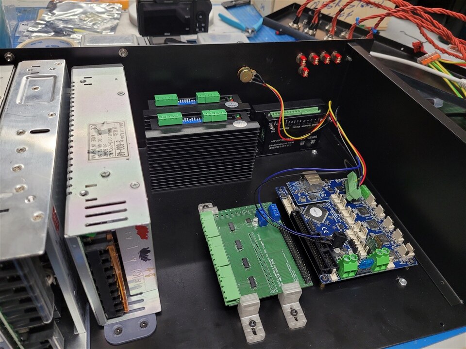
The potentiometer is just a Standard 10k linear Pot (type B) and will be sporting a vintage knob that came of a broken 70s oscillator. Because it has a large diameter it will be easy to make fine adjustments to the spindle speed. As there is no digital control and speed measurement (yet) , we need to be able to adjust it while the machine is running to find the sweet spots and mark these for later reference.
Link to the Poti: https://at.farnell.com/tt-electronics-bi-technologies/p160kn-0qd15b10k/drehpotentiometer-10k-15mm-20/dp/2771753?CMP=e14c-noscript&COM=e14c-noscript

The switches are leftovers from a previous Element14 presents project, where I built an Arduino uno based remote control.
These are great to put directly on PCBs as they fit a standard 2,54mm pattern.
So the footprint for these would be the same as for a 3 position 2,54mm Pin header.
In this case I mount them to the front panel and solder on wires individually. In hindsight, this could also have been a tidy PCB solution. Well maybe next time.
Link to the switches: https://at.farnell.com/multicomp/2ms1t1b5m2re/schalter-leiterplatte-spdt-vert/dp/9473041?CMP=e14c-noscript&COM=e14c-noscript
The huge fan cover fits a 100mm Fan, but I only cut a hole right in the center located directly in front of the internal PSU Fan. This seemingly odd choice is determined by , me happen to have that Cover in stock since 2005,,and never using it for anything. And the biggest size of my hole saw set that is able to cut the steel enclosure is just 35mm wide.
At least its a signature look.
The top bolts block the top cover now, so here is a word of caution to check clearances before committing to a position. and the allignement is slightly off, the Piece must have shifted a bit during Lasermarking , or drilling. So I will have to make a few little grooves in the top cover to account for those Screws.
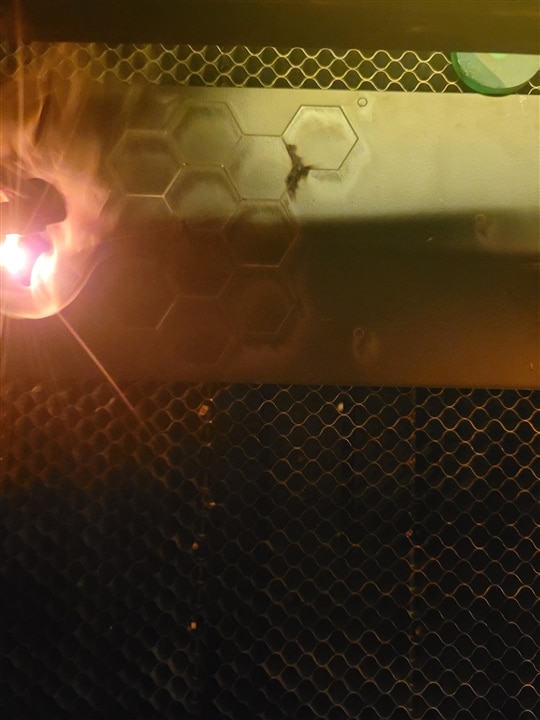
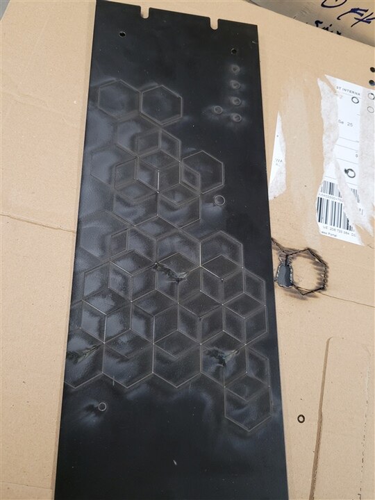
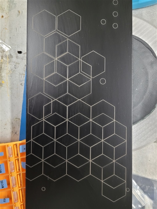
Speaking of Lasermarking:
the obvious thing has to be done, make it look cool with a Geometric pattern.
I decided to use hexagons, as we know they are the "bestagons".
But hexagons also have a neat property that I think suites my machine pretty well. If you line them up and overlap them just right they form a pattern that gives the impression of 3D cubes to the viewers eye.
I tried to represent this process by positioning Hexagons individually on the left and gradually moving more of them into position to form a 3D Cube Pattern.
This represents how 2D shapes or movements together form 3D shapes and isn´t that how a CNC works?
With 2D movements in X,Y,Z a 3d dimensional object emerges and the fourth Axis on my machine adds a a bit more capabilities into the mix.
I designed my pattern directly in Lightburn, the Lasercutter Software I use to run my Machines recently. Before that I would have designed in Inkscape and then moved the result to Visicut to set up the laser job.
But since my newest laser is not supported by the open source Visicut, I caved in to purchase a Lightburn license which I now use across all machines.
I still recommend Visicut highly for Co2 Lasers, but for complicated and big projects Lightburn has the competitive Edge for now.
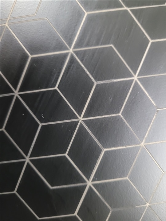
To enhance the 3d effect , I used different thicknesses of lines on the layers of hexagons. The way to do this when burning away powder coating or paint from metal is not by making thicker lines in the design but by separating it on different layers and using different Speed and Power settings.
This is analogous to using a different milling bit on a CNC, while a thicker line can shift the whole pattern or leave a seam in the middle, altering power stays true to the alignment, but just burns deeper or wider depending on the material used. It can be also more obtuse and therefore give the engraving more visual depth.

I hope to make some more wiring progress in the next entry and we will probably talk about the possibility of getting Custom sheet metal parts made for some of the fixtures.
Cheers Clem
This blog is a part of Clem's CNC Control Project. Click the Previous button to jump to the previous blog in the series.
