I was a bit unsure if I want to first finish motor mounting or do the tedious mounting and wiring part in the electronics enclosure.
But the weather took over that decision, because I will use Engineering Resin to 3d print most mounting parts, I need to keep a printing temperature of around 20 °C to ensure perfect flow. Printing at temperatures below 15°C is not advised with any 3d printing Resin, and with an outside temperature of -8 °C ...getting some fresh air into the workshop will cause severe drops anytime I open the window.
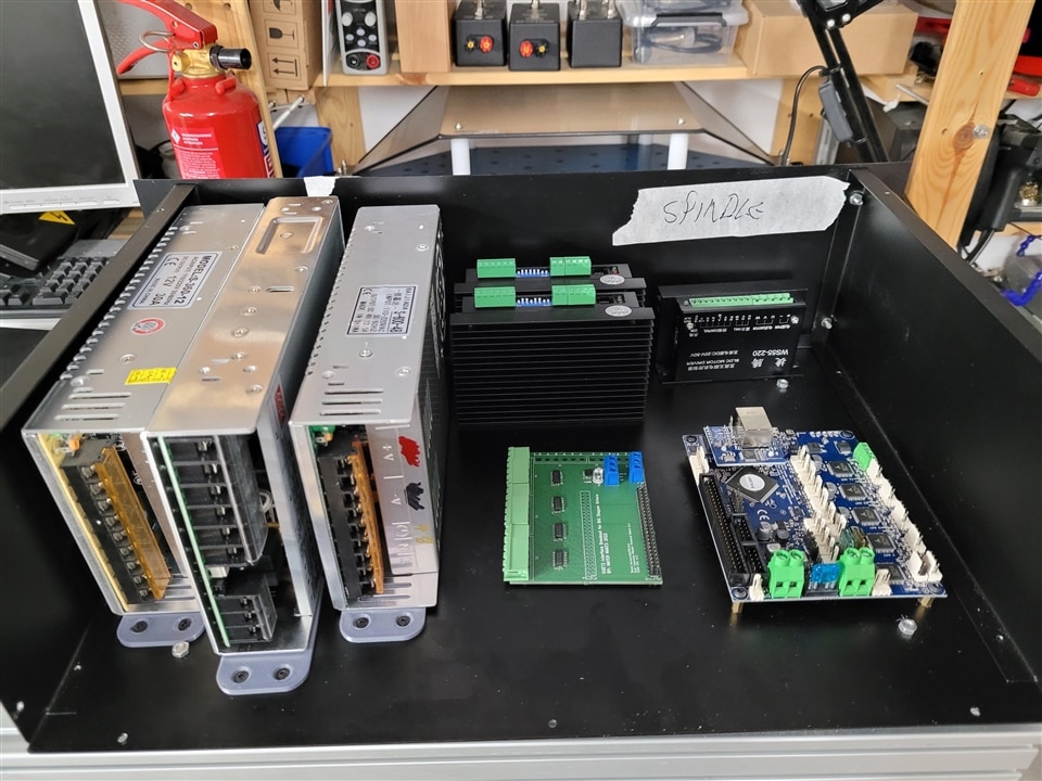
So I decided to start with mounting the stepper drivers, power supplies and control boards into the enclosure. By shear luck the biggest power supply barely fits inside the enclosure flipped on its side.


The Breakout board I designed in the last Episode was, delivered populated and soldered up ready to be mounted inside...only for me to discover I had forgotten to plan in any mounting holes.
Well some 3d printed holders will fix that later.


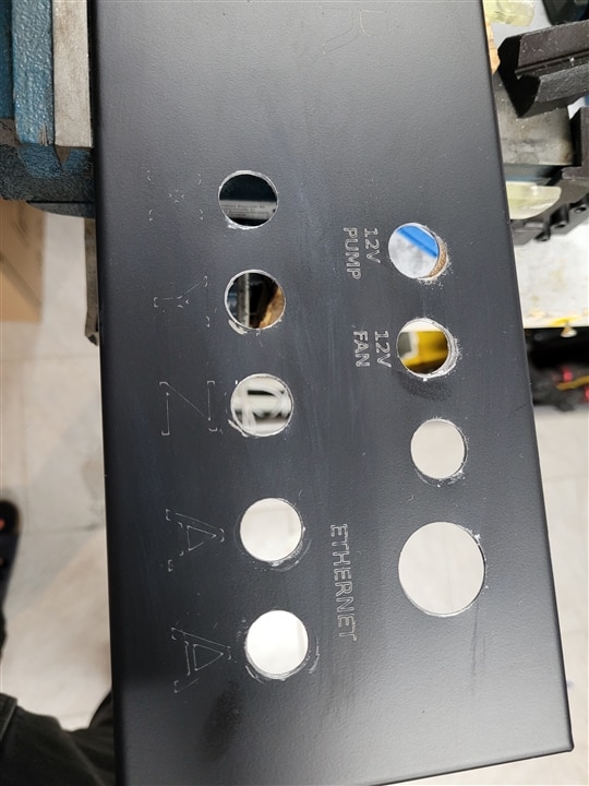
The back panel requires a lot of holes in strategic locations for the connectors that lead to the outside wiring for 230V power input , motors, spindle and additional items.


I designed a template in freecad, to place all these cutouts. I could have either printed it on paper and used some sticky tape to position it on the backplate and mark the locations for drilling, but I decided to use my CO2 laser to mark the positions by cutting through a layer of masking tape.
This process also allowed to add some writing with the laser. you might have spotted that there is no spindle connector planned in int he freecad template....well I forgot that one and later just drilled a hole for it next to the Ethernet jack.


Sadly I scratched up a lot of the surface while mounting the aviation connector in their places.
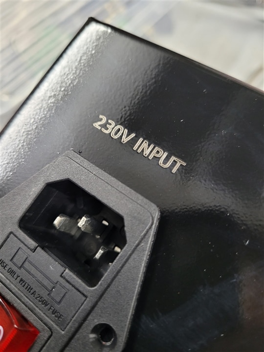
But most of the work was doing the oddly shaped cutout for the power plug and power switch.
I tried out an assortment of methods and tools until settling on a mini cutoff wheel attached to my proxxon rotary tool and a sanding spindle to shape this cutout.

For the round holes required for the aviation connectors I ruined a hole saw intended for wood and unintentionally enlarged one of the DC output connectors intended for Air pumps.
So I caved in and bought the Makita 18V drill I was longing for for years and a set of dedicated steel cutting hole saws. The comparison of fooling around with unsuitable garbage versus using the correct professional tool for the job is astonishing. Clean cuts and very fast drilling was achieved in no time. It was totally worth spending money on good tools.
After adding a coat of white paint to highlight the writing, that did not work as good as intended I cleaned off the plate again and sealed it with clear laquer to avoid rust.


The internal wiring is done with the innards of a Lappkabel Ölflex 3x2,5mm² Cable for the 230V section. I expect to just stay below my outlets rating of 16A at 230V when the machines is in full swing, so substantial wiring was on order.
The Motor wiring has to withstand 48V/4A which results in a minimum conductor width of 0,22mm², so I took 0,5mm² Silicon covered stranded semi-flex wire I bought on Farnell to get an easy to cable manage but also resilient solution.
The same colour (red) is used for all the motor connections while simple DC will be done with a Red/black pair and data connections will get straight black cables.
Not the clearest schemes but I only have to cable colours available at the moment.
the ends were crimped with ferrules or Würth Electronic crimp terminals depending on where they will connect internally. Because I'm left handed I had to resort to the vise clamp holding trick to get the cables all crimped without going insane with the right handed centric tools.
As I have wired up quite a few 3d printers over the years I did not pay much attention to Motor Connector pinouts, as worst case I would just need to swap a maximum of two connections to correct that.
Since nobody has to rebuild another machine based on the exact wiring of mine a simple swap on one end is not as troublesome as with a Kit others have to assemble.
The Motor demands also don’t allow just plug in in the motors into any connection and changing designations in Software, so every motor will only ever be able to be connected to its corresponding port and (mostly) not be interchangeable.


I would like to show you a fully wired unit, but I have to wait for the last set of connectors needed to hock up the power supplies to mains input as well as DC outputs. These will probably not arrive before Christmas, so I have to postpone that to the next blog, where I also want to tackle the outside wiring.
The front Panel will be visible most of the time and has to have at least a minimal User interface,
consisting of a Spindle activation button and a Speed control potentiometer. Maybe this will be replaced with a digital controller one day,but I go for the simple option first.
In any case a cutout for airflow has to be done (thankfully I now got suitable hole saws), maybe this is a chance to be creative.
If you have an idea for a pattern that can be done with just with drills of different diameters, that would be awesome!
Do you see troubles with the wiring? Maybe I’m missing some crucial aspect?
Merry Christmas and a Happy New Year! I hope it won't be to many 2023 posts in this series until the CNC is moving!
This blog is a part of Clem's CNC Control Project. Click the Previous button to jump to the previous blog in the series.

Top Comments