We have talked about electronics and ideas around my cnc project, but its time to get stuff together in an orderly fashion to form the shape of a CNC mill instead of a pile of parts.
My overall concept for the kinematic arrangement is revolving around finding an axis assembly that does not whip around to much mass and has a small footprint compared to the working area.
While there are countless ways of optimizing size to working area ration (CoreXY, H-Bot and more come to mind) my design has to use parts I already have that used to be part of a big industrial 3d printer.
I happen to have 3 CCM rail systems, two together in a pair should move the X Axis back and forth while the third one forms the Y axis and carries the Z axis and the router.
The 4th Axis(A or B) could be mounted in various configurations.
My first idea was to mount a big table on the X axis and bolt the A axis onto it in case I need it.
But there are some issues with this seemingly simple solution:
traming (making sure the axis is perpendicular to all the others)
removal of material (where do chips and coolant go?)
weight
actual usage
| {gallery}Mounting the Axis |
|---|
 |
 |
 |
 |
 |
 |
 |
 |
 |
 |
I know I won't use this cnc mill for big flat pieces so there is no point in having a big flat bed. but there is a good point for having two support points for big workpieces mounted in a chuck when doing 4 axis operations. Like with lathework, supporting the workpiece to keep it stable and chatter free is essential.
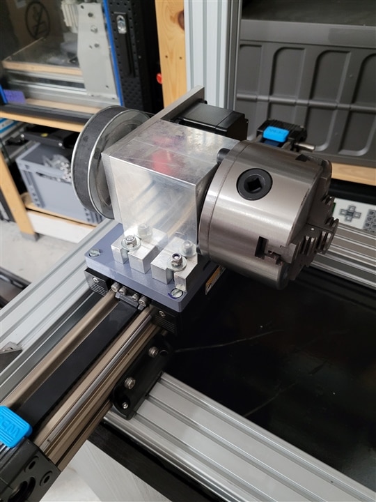
I decided to mount my dual 4th Axis chucks on each of the X carriages.
the movement is synced via a hardened Steel rod that I was not able to cut to size by now, since it is, in fact a very well hardened steel rod.
So I'll have to break out serious power tools to cut it down to size.
the 4th Axis motors are independently controlled but I will sync the driver circuitry via software definition, so in case I have a special case that needs them to not move in snyc, I'm able to do that.
the actual mounting turns out to be a bit tricky.
the bolt patterns of the CCM rails and the 4th Axis mounting block as well as the Z axis (which is a cheap Chinese ball screw driven 100mm movement linear assembly for now) do not line up favorably).
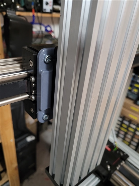
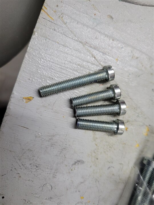
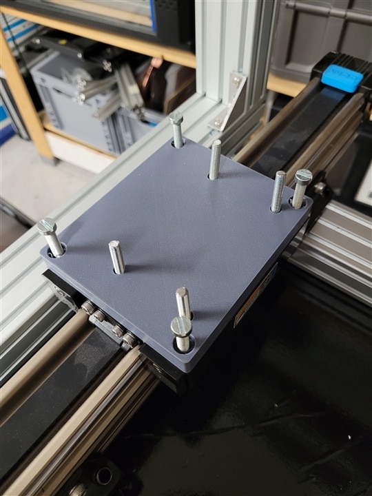
3D printing to the rescue, the only way I could think of to mount these is to have captive screws embedded in the mounting piece(Adaptor plate), these provide mounting studs to which I could bolt the 4th Axis after first mounting said plate to the CCM Rails.
There is only one correct order of operations as I would not be able to reach any other mounting holes after bolting down the 4th Axis mount.
A quick design in Freecad (thankfully the bolt pattern uses full 0,5cm increments) and a round of 3d printing in multicomp petg, which has proven sturdy enough for fit tests of heavy parts, confirmed that my idea does indeed work.
The captive hex heads of some screws did strip the 3d print after tightening the assembly down, so PETG is surely not what can be used for the real assembly.
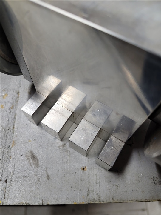
But I'm not willing to spend a lot of money on big chunky aluminum stock to machine these parts myself. It might be more cost effective to get them milled by a service as the raw stock can sometimes be more expensive than final parts from a supplier.
You may know that I'm myself now distributing my own brand of insanely tough 3d printable Engineering Resins and this application seems to be a perfect fit.
While I assume that over long term the durability of a milled aluminum part will surpass even the strongest Resin 3d print, the ease of manufacturing and the much lower price for the parts makes me confident that being able to quickly make a new mounting part whenever one wears out in house might save me quite a lot of money over the machines live.
It also would allow me to continuously improve the geometry and performance during my actual use.
So I will give it a go and maybe after long time of use commit to a final design that I will then machine in metal for permanent usage.
Of course i roughly trammed in and screwed tight all the frame rails
and test mounted the Axis. Having the lathe chucks on both sides of the machine with a lot of space beneath them gives me ample room for a chip tray and coolant collector as well as allows the sides to be closed off and used for mounting lights or protective panels.
I personally like to have open machines so I can directly see if something goes wrong inside, but I'm not keen on hot metal shrapnel piercing my eyes, so being able to close off the whole machine with some paneling is a task I'm looking forward to.
It also would make the whole machine look a lot less janky.
Here is a question for all the community members:
Would you mount the electronics in the cabinet beneath the machine or above it?
the bottom can be used for coolant tank and material storage, but I`m a bit worried having to much weight on top might lead to increased vibrations compared to a bottom heavy design. Having the electronics on top would ensure there is no chance of coolant running into the electronics cabinet or chips finding their way to short out power supplies etc.
What's your opinion?
Also do you agree with my Choice of Axis arrangement or do you have a better idea given the parts at hand?
thanks for joining in again.
Clem
This blog is a part of Clem's CNC Control Project. Click the Previous button to jump to the previous blog in the series.

-

dougw
-
Cancel
-
Vote Up
0
Vote Down
-
-
Sign in to reply
-
More
-
Cancel
-

mayermakes
in reply to dougw
-
Cancel
-
Vote Up
0
Vote Down
-
-
Sign in to reply
-
More
-
Cancel
Comment-

mayermakes
in reply to dougw
-
Cancel
-
Vote Up
0
Vote Down
-
-
Sign in to reply
-
More
-
Cancel
Children