


The community has spoken.
In the last Blog post I've asked you about the positioning of the electronics cabinet.
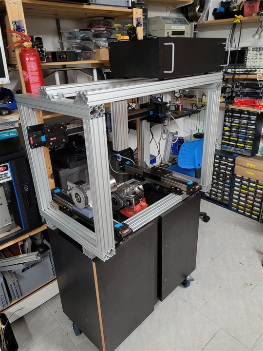
And by far the most popular choice was to put it above the whole machine where no splinter, chip or Dash of coolant can go.
So i took that advice and decided to mount the electronics in a 3HE Rack mount enclosure I had in stock
(bought it on occasion for the teletype project on Element14presents, but I did not use it: /challenges-projects/element14-presents/project-videos/w/documents/27606/episode-549-using-a-teletype-machine-as-a-usb-printer-with-arduino)
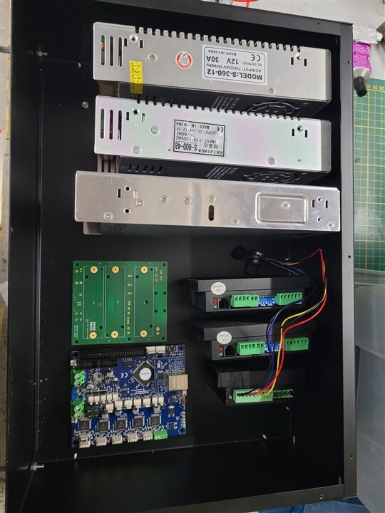
The 3 HE proved to be exactly (and I mean to the mm) the required height to mount the Power supplies on their side. This allows all 3 Power supplies, the big DM556 Stepper drivers, and a duet2 Ethernet control board as well as the BLDC controller for the spindle to be mounted within this Rack mount enclosure.
Refer to my janky drawn layout diagram and photos.
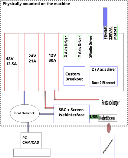
the connections to the outside world will be done with a variety of Aviation connectors for the stepper motors, air pump and whatever I want to add later, as well as Ethernet and the 230V Power input.
A Separation inside the case to prevent EMF cross talk might be needed. I hope to get good advise on this topic from you, my dear Readers!
There is still a bit of space left in the case and a question to answer.
How do you connect a duet2 to big external Steppers?
The outputs of the duet 2 are meant to directly drive Stepper motors with the internal TMC2660 Drivers.
We use 3 of these outputs for the Z Axis and the dual rotary Axis(A/B).
But the X & Y Axis need to be interfaced with a STEP/DIR type interface.
Despite there being labeled pins (EN/STP/DIR) next to each driver on the duet2 board, these cannot be used to drive any driver, and are just there as debug points to hook up an oscilloscope.
These points cannot drive the pins of a stepper driver and it would even be the wrong "format" for the DM556 modules.
I have tried years earlier when the duet2 was brand new on the market to utilize them with no success, even hooked up to an amplifier these pins are not suitable.
But there is another row of connections available.
The expansion header is meant to connect to the duex5 and add 5 more motor drivers and other ports to the System.
Duet3D offered a special breakout board for this connector to level shift and reformat the STEP/DIR/EN signals into a usable signal for Big Stepper drivers just like my DM556. I have used this board before when I worked on an industrial 3d printer prototype back in 2018.
Looking up the listing on duet3ds website showed it as out of production. No wonder, since its now generations old and I imagine that the demand for this board was surely not as big as for the actual controller boards.
A quick web search resulted in lots of listings but I did not really trust the sources and the price seemed a bit to high for my taste on any listing i might have considered.
The beauty of open source Hardware.
A click on the documentation solved all of my troubles, the desired breakout board is Open source Hardware.
duet3d posted all the schematics on their Github when the Design was released. it even was done in Kicad.
A download later and some little hiccups with conversion from the old filesystem to the current Kicad 6 system i had a Layout in front of me that I could send directly in production.
But I decided to do something different.
I'm all for building on Open source projects, but I'm also not a fan of straight up Clones, at least not when I can add something to it or make the device a tiny bit better suited for my specific needs.
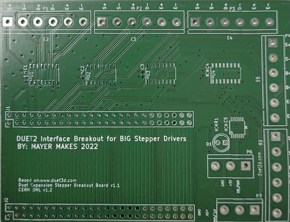
So I decided to fork the project and design a derivative using the original schematics.
https://github.com/mayermakes/Duet-2-Hardware
My version is a lot bigger than the original design, but is also more convenient to use with chunky drivers and cables.
I've replaced the 2,54mm headers designed for JST plugs (I hate crimping) with 5.08mm spaced chunky screw terminals.
Added a power led for convenience.
Doubled up the expansion header, so in case I wanted to add the duex5 later, I would not have to weirdly splice in another connector on the Ribbon cable like the original was designed to do (covering the other conenctors in the process rather inconveniently.
the secondary header allows to use a separate 50pin Ribbon cable to move on towards a duex5 or just break out any connection I may need in addition to my derivative breakout board.
I ordered the board at Aisler.net which I commonly use for all my PCB needs and got the generic 74 series ICs needed on Farnell.com
The PCB has arrived the day I'm writing this Blog post. So you can expect to see the assembled version in the next one.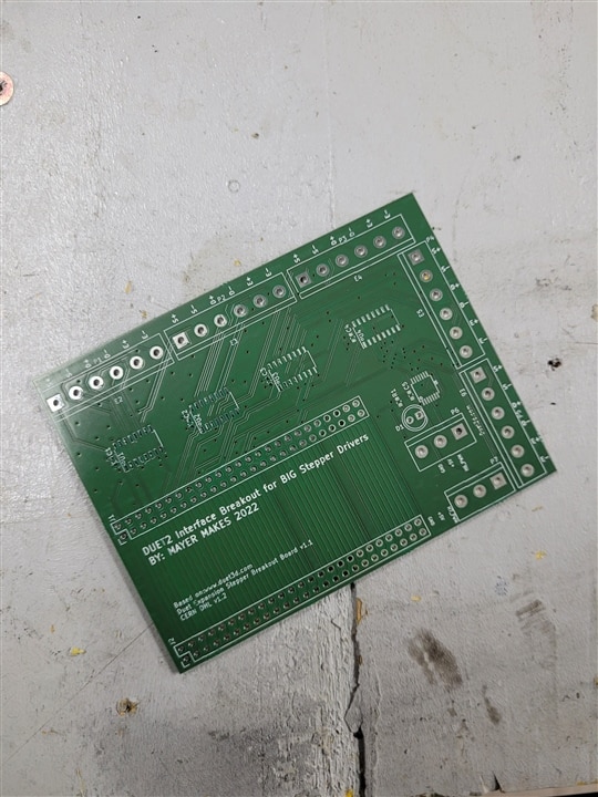
But before I bolt all the parts down in the box I want to get some feedback from you about my box layout.
Do you think there could be EMF problems?
Would you lead out Ethernet on the back or front?
Should the safety cutoff be on the box or externally mounted on the frame of the machine?
Any recommendations for the power cable?
cheers
Clem
This blog is a part of Clem's CNC Control Project. Click the Previous button to jump to the previous blog in the series.
-

dougw
-
Cancel
-
Vote Up
0
Vote Down
-
-
Sign in to reply
-
More
-
Cancel
-

mayermakes
in reply to dougw
-
Cancel
-
Vote Up
0
Vote Down
-
-
Sign in to reply
-
More
-
Cancel
-

dougw
in reply to mayermakes
-
Cancel
-
Vote Up
0
Vote Down
-
-
Sign in to reply
-
More
-
Cancel
Comment-

dougw
in reply to mayermakes
-
Cancel
-
Vote Up
0
Vote Down
-
-
Sign in to reply
-
More
-
Cancel
Children