I know this seems out of context, but please take a few seconds to read through before deciding that I'm not only in the wrong tree, but also the wrong orchard.
I have a model train locomotive (N-scale, Bachmann Spectrum GE Dash 8-40C) that I am converting from DC to DCC. I'm told by another source to "remove the two chokes (inductors?) from the PCB" and solder the connections from the DCC decoder to the PCB. I'm leery about removing these components as I don't understand what they do and why it would be OK to remove them.
I'm willing to bet money that it's OK, but I want to understand the components and the process better. In an attempt to do that, I thought I would try to replicate the circuit (as much as I can) using Eagle and maybe learn what's going on. The roadblocks I have encountered so far are that I can't find a 15VDC source and I can't find a can motor (or any kind of motor) to insert into the circuit.
The motor circuit is very simple: A 15VDC source, a 4.7uH inductor on each lead going to a DC can motor. (The lighting circuit is more complex with diodes, resistors, capacitors and LEDs - Perhaps I'll deal with that later in another post.)
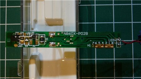
Top of PCB:
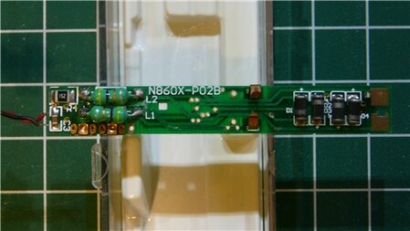
Bottom of PCB:
Can anyone shed light on:
how to include the components I'm looking for?
what the inductors do?
why it's OK to remove them?
anything else you could bestow upon me?
Thanks in advance.
Mozarelli


