


Introduction
Traditional home security systems have long relied on a centralized architecture. All of the signal processing and control logic lives in a single, often bulky, cabinet. The user interface is usually just a simple keypad used for arming and disarming the system, with status information presented on a two-line LCD. While this approach works, it offers very little flexibility when it comes to monitoring or integrating individual sensors. Of course, with more modern, more expensive, systems have solved this with cellular and wifi connectivity but you tend to have to pay a monthly/annual subscription for this service.
With the Smart Security and Surveillance Design Challenge about to start soon (I’m merely spectating), I decided to share this little first-cut board design with the e14 community as a design-thinking warm-up exercise. It’s been sitting in a box not doing much - and for good reason too.
If you're curious, read on.

My crude design was largely inspired by the Seeed Studio XIAO series of modules. These tiny boards provide the powerful “brains” (you have a choice of ESP32, nRF and MG24 MCU’s) and offer a wide range of wireless options. They also offer great flexibility thanks to their common pinout. With only minor adjustments, the same board concept could easily be adapted for other microcontroller ecosystems, such as boards using the Feather footprint.
I called it a universal transmitter node because it acts as a hardware bridge between traditional alarm sensors and your home router (for cloud connectivity) or home automation system (take your pick on wireless communications protocol). Almost any dry-contact or open-drain sensor can be connected, along with serial encoded wired data transmission. Instead of producing a simple alarm signal, you can program the node to transmit structured sensor data using whatever wireless protocol you prefer.
The objective was to create a node capable of interfacing with up to four existing hard-wired, open-drain off-the-shelf sensors, such as PIR (passive infrared) motion detectors. The aim was to simply convert open drain to digital logic, apply some “smarts” with MCU algorithms and transmit via a standard wireless protocol. The node essentially provides a clean abstraction layer that can feed almost any smart-home or automation platform.
This design is still very much a work in progress and full of beginner mistakes. It was my first attempt at optimizing a well-trodden circuit for robustness and cost, and there are almost certainly mistakes. By sharing the design early, I'm hoping to draw out alternative ideas and refinements from the community.
Hardware Design

The board is made up of the following features:
- A 12V to 5V DC-DC Converter - most home security systems work off 12V hence the target input voltage
- Polarity protection to ensure that the output voltage is also not reversed.
- Open drain to digital signal conversion
- Tamper switch to notify if board enclosure opened
- Buzzer for local audible notification
- LED’s for local HMI (human-machine interface)
- Screw terminals for I/O interface
- Microcontroller - in this case a Seeed Studio Xiao dev-board.
My primary goal was to keep it low cost and to keep it simple. In terms of design decisions these were the key ones I made.
For the 12V to 5V DC-DC power conversion, a common 1117 (“jelly bean”) voltage regulator was selected. It’s been around for awhile and it’s a popular choice - they’re widely used on dev boards such as esp8266’s, esp32’s, and the Arduino UNO and Mega 2560 platforms. These Low-Dropout (LDO) regulators provide 800mA up to 1A, which makes it suitable for modern microcontrollers like those on the Xiao dev boards. What makes this attractive is that at a minimum it only requires two additional capacitors.

Naturally, I acknowledge the existence of more power-efficient and thermally superior alternatives (e.g. TI TPS542025DDCR). Therefore, I would be curious to know what others would have chosen for this design.
The next key design decision was determining how best to convert an open drain output from the sensor/detector to a digital input signal for the MCU.
Here I went for another “jelly bean” low cost component, namely a LM2901 quad channel comparator. This open-collector comparator allows input voltages much higher than its own supply rail, so it potentially could be powered using 5V or 3V3 while the input signal could be 12V. As you can see from the schematic, I powered the LM2901 using a 12V supply too.
In hindsight I think over complicated matters by using a separate voltage reference (1.25V) for the negative input voltage. I should probably have just used a voltage divider instead. What would you do?

As an alternative design, I did consider using a quad opto-isolator, such as the Lite-On LTV-847S (or equivalent) but then got bogged down with all the power and current calculations.
As such, I would be curious to know what others would have chosen for this design.
To help with your evaluation, here is the schematic and PCB design:
| {gallery:autoplay=false}Board Design |
|---|
|
|
|
|
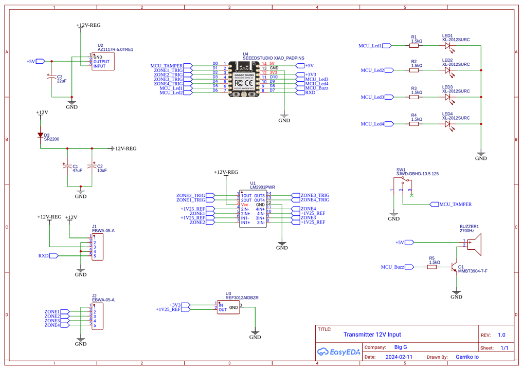

The obvious mistake I made on this board was with the Tamper switch. The idea was simple. Apply an INPUT_PULLUP on MCU_TAMPER input and measure when it goes to 0V. However, it didn’t work. I am sure you can explain why and I am curious to know what you’d do differently.

I then added a buzzer and LED’s to handle the onboard UI. The active buzzer can be powered with 3V up to 7V DC. It has a built-in driving circuit which produces 80dB output at 2.7kHz resonant frequency, and consumes up to 30mA when active.

There was one oversight on my part. I forgot to add a flyback diode to protect the circuit from the electromagnetic transducer back-EMF spike. Maybe it’s overkill considering I have a MMBT3904 transistor driving the load. What are your opinions on this matter?
Then there is one todo on my part. The RX channel does not include any level shifting, which means that it needs to be at a 3V3 logic level.
There are a number of design choices to consider if I wanted the logic level to be at 12V, for example. But as I have not researched this part as yet, I am open to suggestions.
For example, do I use something like a MAX3232E device, which according to the datasheet, consists of two line drivers, two-line receivers, and a dual charge-pump circuit
with ±15-kV IEC ESD protection pin to pin (serial-port connection pins, including GND). Maybe this option only helps with RS232. Maybe it’s overkill.
Or do I follow Sparkfun's bipolar transistor based design? I have used this before and it worked great.
Or would a bidirectional/unidirectional voltage-level translator work. It’s my assumption that there’s not much available if the logic level voltage is greater than 5.5V and most unidirectional options are TTL to CMOS or CMOS to CMOS only. Thoughts?
Firmware Design
The Xiao development boards offer plenty of flexibility when it comes to choosing a suitable firmware development environment. Options include the Arduino platform, Zephyr RTOS, or even the manufacturer's specific integrated development environment, such as ESP-IDF (for ESP32’s) or Simplicity Studio (for MG24’s), for example.
As the Zephyr RTOS ecosystem has recently become my go-to choice, I will demonstrate how easy Zephyr actually is (once setup). I will use the Xiao ESP32-S3 board for this purpose.

To develop this application, I started with the Zephyr blinky example and built from there. The first thing we need to do is define our hardware in the application’s board device tree.
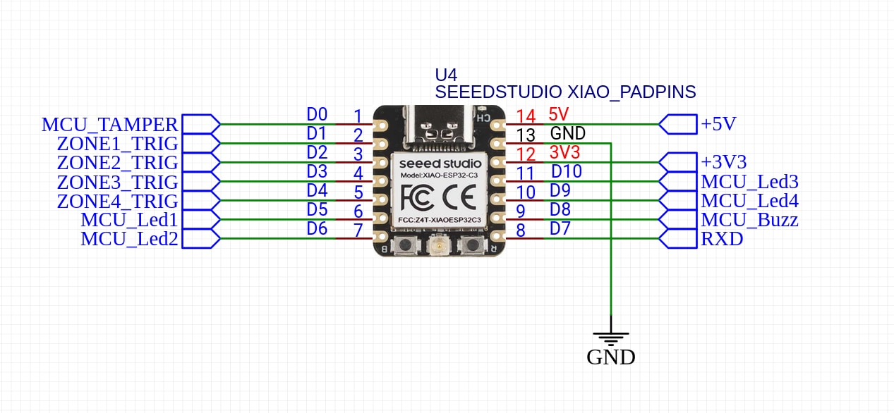
Looking at the schematic, we can see that the tamper switch is tied to D0 (Arduino), which is GPIO1 for Zephyr. The four zone inputs are tied to D1 through to D4. The LED outputs are connected to D5, D6, D10 and D9. Finally buzzer is using D8.
To help figure out the Zephyr GPIO’s we could use the xiao_d: connector GPIO mapping as defined in “seeed_xiao_connector.dtsi”, or as I prefer, I use this file as my reference when determine the Zephyr GPIO pin numbers.
/*
 * Copyright 2026,BigG
 *
 * SPDX-License-Identifier: Apache-2.0
 */

#include <zephyr/dt-bindings/input/input-event-codes.h>

/ {

  	zephyr,user {
        /* Using a user node to group the input GPIO's (D1, D2, D3, D4)*/
        trigger-gpios = <&gpio0 2 (GPIO_PULL_UP | GPIO_ACTIVE_LOW)>,
                       <&gpio0 3 (GPIO_PULL_UP | GPIO_ACTIVE_LOW)>,
                       <&gpio0 4 (GPIO_PULL_UP | GPIO_ACTIVE_LOW)>,
                       <&gpio0 5 (GPIO_PULL_UP | GPIO_ACTIVE_LOW)>;

        led-gpios = <&gpio0 6 GPIO_ACTIVE_HIGH>,
                    <&gpio1 11 GPIO_ACTIVE_HIGH>,
                    <&gpio0 9 GPIO_ACTIVE_HIGH>,
                    <&gpio0 8 GPIO_ACTIVE_HIGH>;

        buzzer-gpios = <&gpio0 7 GPIO_ACTIVE_HIGH>;
	};

	aliases {
		sw0 = &tamper_switch;
	};

	gpio_keys {
		compatible = "gpio-keys";
    	status = "okay";
		polling-mode;
		tamper_switch: button_0 {
			label = "Tamper Switch";
			gpios = <&gpio0 1 (GPIO_ACTIVE_LOW | GPIO_PULL_UP)>;
      		zephyr,code = <INPUT_KEY_0>;
		};
	};

};

/* Disable the existing UART0 so it doesn't initialize with old settings */

&i2c0 {
	status = "disabled";
};

&spi2 {
	status = "disabled";
};

&pinctrl {
	uart0_rxonly: uart0_default {
		group2 {
			pinmux = <UART0_RX_GPIO44>;
			bias-pull-up;
		};
	};
};

/* Re-enable and reassign UART0 with new settings */
&uart0 {
    status = "okay";
    current-speed = <115200>;
    pinctrl-0 = <&uart0_rxonly>;
    pinctrl-names = "default";
};
In this device tree I used “zephyr,user” as my method to define my IO’s such as the trigger zones and the LED’s. This is a really handy abstraction method.
As this example just uses GPIO’s there is nothing I needed to add to the “prj.conf” file. When developing your application it’s always worth checking the board’s default configuration settings. These can be found in the “xiao_esp32s3_procpu_defconfig” file.
Then it’s a case of coding. Here is main.c. The application uses a callback to handle zone triggers and timers to handle the LED’s and buzzer.
/*
 * Copyright (c) 2026 BigG
 *
 * SPDX-License-Identifier: Apache-2.0
 */

#include <stdio.h>
#include <zephyr/kernel.h>
#include <zephyr/drivers/gpio.h>
#include <zephyr/sys/printk.h>

/* 1000 msec = 1 sec */
#define SLEEP_TIME_MS   1000

/* The devicetree node identifier for the "led0" alias. */
#define LED0_NODE DT_ALIAS(led0)
#define LED_ZONES DT_PROP_LEN(DT_PATH(zephyr_user), led_gpios)
#define TRIG_ZONES DT_PROP_LEN(DT_PATH(zephyr_user), trigger_gpios)

static const struct gpio_dt_spec led = GPIO_DT_SPEC_GET(LED0_NODE, gpios);

/* Initialize the array of GPIO specs using the index-based macro */
static const struct gpio_dt_spec trigger_zones[] = {
    DT_FOREACH_PROP_ELEM_SEP(DT_PATH(zephyr_user), trigger_gpios, GPIO_DT_SPEC_GET_BY_IDX, (,))
};

static const struct gpio_dt_spec zone_leds[] = {
    DT_FOREACH_PROP_ELEM_SEP(DT_PATH(zephyr_user), led_gpios, GPIO_DT_SPEC_GET_BY_IDX, (,))
};

static const struct gpio_dt_spec buzzer =
    GPIO_DT_SPEC_GET(DT_PATH(zephyr_user), buzzer_gpios);

static struct gpio_callback sensor_cb_data;

static struct k_timer led_timers[TRIG_ZONES];
static struct k_timer buzzer_timer;

static void led_timer_handler(struct k_timer *timer_id)
{
    int idx = (int)(intptr_t)k_timer_user_data_get(timer_id);
    gpio_pin_set_dt(&zone_leds[idx], 0);
}

static void buzzer_timer_handler(struct k_timer *timer_id)
{
    gpio_pin_set_dt(&buzzer, 0);
}

void trigger_isr(const struct device *port, struct gpio_callback *cb, uint32_t pins) {
    for (int i = 0; i < ARRAY_SIZE(trigger_zones); i++) {
        if (pins & BIT(trigger_zones[i].pin)) {
            /* Turn on corresponding LED and start its cancel timer */
            gpio_pin_set_dt(&zone_leds[i], 1);
            k_timer_start(&led_timers[i], K_MSEC(2000), K_NO_WAIT);

            /* Turn on buzzer and start its cancel timer */
            gpio_pin_set_dt(&buzzer, 1);
            k_timer_start(&buzzer_timer, K_MSEC(600), K_NO_WAIT);
        }
    }
}

int main(void)
{
	int ret;
	uint32_t pin_mask = 0;
    int current_led = 0;
	bool led_state = true;

	if (!gpio_is_ready_dt(&led)) {
		return -1;
	}

	ret = gpio_pin_configure_dt(&led, GPIO_OUTPUT_ACTIVE);
	if (ret < 0) {
		return -1;
	}

	/* Initialize and configure all Input Zones in the array */
    for (int i = 0; i < TRIG_ZONES; i++) {
		/* Ensure GPIO controller is initialized */
        if (!device_is_ready(trigger_zones[i].port)) {
            return -1;
        }

        /* Configure pin using Devicetree flags (Pull-up + Active Low) */
        gpio_pin_configure_dt(&trigger_zones[i], GPIO_INPUT);

        /* Set interrupt to trigger on both edges to capture any state change */
        gpio_pin_interrupt_configure_dt(&trigger_zones[i], GPIO_INT_EDGE_BOTH);

        pin_mask |= BIT(trigger_zones[i].pin);

        /* Initialize the turn-off timer for this zone's LED */
        k_timer_init(&led_timers[i], led_timer_handler, NULL);
        k_timer_user_data_set(&led_timers[i], (void *)(intptr_t)i);
	}

	/* Initialize and configure all LEDs in the array */
    for (int i = 0; i < LED_ZONES; i++) {
        if (!device_is_ready(zone_leds[i].port)) {
            return -1;
        }
        // Initialize as output and start with the LED turned OFF
        gpio_pin_configure_dt(&zone_leds[i], GPIO_OUTPUT_INACTIVE);
    }

	if (!device_is_ready(buzzer.port)) {
        return -1;
    }

	/* Configure as output, initially OFF */
    gpio_pin_configure_dt(&buzzer, GPIO_OUTPUT_INACTIVE);
    k_timer_init(&buzzer_timer, buzzer_timer_handler, NULL);


	/* Create UI output to indicate powered on a ready */
    for (int i = 0; i < 12; i++) {
		gpio_pin_set_dt(&zone_leds[current_led], 1);

		k_msleep(200); // Wait 200ms

		/* Turn OFF the current LED */
		gpio_pin_set_dt(&zone_leds[current_led], 0);

        /* Move to the next LED (wrap back to 0 at the end) */
        current_led = (current_led + 1) % LED_ZONES;
    }

	gpio_pin_set_dt(&buzzer, 1);
	k_msleep(300);
	gpio_pin_set_dt(&buzzer, 0);
	k_msleep(300);
	gpio_pin_set_dt(&buzzer, 1);
	k_msleep(300);
	gpio_pin_set_dt(&buzzer, 0);
	k_msleep(300);
	gpio_pin_set_dt(&buzzer, 1);
	k_msleep(500);
	gpio_pin_set_dt(&buzzer, 0);

	gpio_init_callback(&sensor_cb_data, trigger_isr, pin_mask);
    gpio_add_callback(trigger_zones[0].port, &sensor_cb_data);

	while (1) {
		ret = gpio_pin_toggle_dt(&led);
		if (ret < 0) {
			return 0;
		}

		led_state = !led_state;
		printk("LED state: %s\n", led_state ? "ON" : "OFF");
		k_msleep(SLEEP_TIME_MS);
	}
	return 0;
}
And here’s a short demo of the basic application in action.
Next steps
As you can tell, this hardware project is still not finished. Maybe the “Spring Clean” competition is my motivation to get the next design iteration done… with a little help from yourselves, of course.
I hope you found this blog useful.

