element14 Community
element14 Community
    Register Log In
  • Site
  • Search
  • Log In Register
  • Community Hub
    Community Hub
    • What's New on element14
    • Feedback and Support
    • Benefits of Membership
    • Personal Blogs
    • Members Area
    • Achievement Levels
  • Learn
    Learn
    • Ask an Expert
    • eBooks
    • element14 presents
    • Learning Center
    • Tech Spotlight
    • STEM Academy
    • Webinars, Training and Events
    • Learning Groups
  • Technologies
    Technologies
    • 3D Printing
    • FPGA
    • Industrial Automation
    • Internet of Things
    • Power & Energy
    • Sensors
    • Technology Groups
  • Challenges & Projects
    Challenges & Projects
    • Design Challenges
    • element14 presents Projects
    • Project14
    • Arduino Projects
    • Raspberry Pi Projects
    • Project Groups
  • Products
    Products
    • Arduino
    • Avnet Boards Community
    • Dev Tools
    • Manufacturers
    • Multicomp Pro
    • Product Groups
    • Raspberry Pi
    • RoadTests & Reviews
  • Store
    Store
    • Visit Your Store
    • Choose another store...
      • Europe
      •  Austria (German)
      •  Belgium (Dutch, French)
      •  Bulgaria (Bulgarian)
      •  Czech Republic (Czech)
      •  Denmark (Danish)
      •  Estonia (Estonian)
      •  Finland (Finnish)
      •  France (French)
      •  Germany (German)
      •  Hungary (Hungarian)
      •  Ireland
      •  Israel
      •  Italy (Italian)
      •  Latvia (Latvian)
      •  
      •  Lithuania (Lithuanian)
      •  Netherlands (Dutch)
      •  Norway (Norwegian)
      •  Poland (Polish)
      •  Portugal (Portuguese)
      •  Romania (Romanian)
      •  Russia (Russian)
      •  Slovakia (Slovak)
      •  Slovenia (Slovenian)
      •  Spain (Spanish)
      •  Sweden (Swedish)
      •  Switzerland(German, French)
      •  Turkey (Turkish)
      •  United Kingdom
      • Asia Pacific
      •  Australia
      •  China
      •  Hong Kong
      •  India
      •  Korea (Korean)
      •  Malaysia
      •  New Zealand
      •  Philippines
      •  Singapore
      •  Taiwan
      •  Thailand (Thai)
      • Americas
      •  Brazil (Portuguese)
      •  Canada
      •  Mexico (Spanish)
      •  United States
      Can't find the country/region you're looking for? Visit our export site or find a local distributor.
  • Translate
  • Profile
  • Settings
Open Source Hardware
  • Technologies
  • More
Open Source Hardware
Blog ESP8266 interface board on it's way (WifIco)
  • Blog
  • Forum
  • Documents
  • Events
  • Polls
  • Members
  • Mentions
  • Sub-Groups
  • Tags
  • More
  • Cancel
  • New
Join Open Source Hardware to participate - click to join for free!
  • Share
  • More
  • Cancel
Group Actions
  • Group RSS
  • More
  • Cancel
Engagement
  • Author Author: camuyano
  • Date Created: 8 Nov 2014 7:22 PM Date Created
  • Views 1301 views
  • Likes 4 likes
  • Comments 10 comments
  • wifi
  • hardware
  • hardware_design
  • internet_of_things
  • open
  • esp8266
  • arduino
Related
Recommended

ESP8266 interface board on it's way (WifIco)

camuyano
camuyano
8 Nov 2014

If you do not know what the ESP8266 is... oh boy. It is a cheap WIFI Uart module (google it).

I have been playing around with the ESP8266 for a few days now. While doing my testing I realized that most of the time my problems are faulty wiring. Yeah I know, noob right. Well what can I say, I am a noob. Anyhow it is frustrating trying to debug software problems while still having hardware issues.

This week while reading on the web found a service that can manufacture a PCB for $5 per square inch for 3 boards and it is made in the US. I am not in continental US but close enough. Also it says the part will be sent back in 12 days (more or less). The service is not important, the important is that my mind ran very quickly.

Would I be able to do a 1x1 inch pcb to interface my ESP8266 delicate 3.3V signals to my strong 5V Arduino ?..... CHALLENGE ACCEPTED!

After a few Eagle Cad iterations (about 3 or 4 in 2/3 days) I came up with a simple board that is suppose to be able to do that. BUYA! It shall be called "WifIco".


Ok all this sounds very quickly and it's because it has been. I didn't even mounted a breadboard prototype before ordering. This one goes all or nothing. For a while I have been wanted to do a pcb using smd components and this sounded like a good chance for it. And very important keeping the design on the $5 mark (there is not that much money to spare here you know).


Board Features

  • Power input of 5V
  • RX and TX signals 5V friendly
  • 3.3V regulated output
  • Breadboard friendly pin out
  • Space at the bottom for a mini usb port in case the device is firmware programmed and need a power input from a cell phone charger or something. Wanted a micro usb but I think I have salvaged a mini usb port someplace around
  • GPIO0 and GPIO2 exposed (not 5V friendly, be careful)
  • Connector to plug in the ESP8266 directly to the board.


Note:

On the bottom side there are two resistors that should be solder shut to pull RST and CHPD to high. They are just put there in case I needed to use the board for firmware upgrade or needed them. From the schematic capacitor values do not mean nothing. Should check on 3.3V regulator circuit guide lines for actual values. If input voltage is clean you may skip them ( but don't tell anybody I said that).


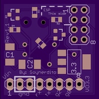
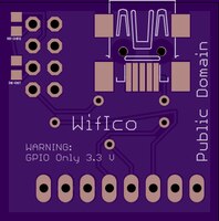
This is how WifIco will looks like (at least from the images from the OSHPark web site):

image

Top Side

image

Bottom side


My eagle design files are here. All is on Public Domain licensing if anybody wonder. I do not need mention nor credit for nothing you do with this.


This may or may not work, in a few weeks I will know! If you don't ever build it or at least try it you'll never now.


Update:

I received an email from the manufacturing service that says, the board was sent to factory on Nov 10 and should be back from factory on Nov 20. After that I guess mailed back to me (+5 more days). My guess is that in best case scenario I will be posting on results back somewhere during December (I hope). Still I am exited about the success of this project and hope you are too.


Update 2 (Nov20):

I received a new email that says, board was received from factory and was shipped to me. This occurred on nov 19, 2014. Today is the 20th. Normally this things take anything from 2 days to 7 days to get here. As soon as I have it with me, the plan is to do a continuity test on the contacts and solder the parts for full testing.


Update 3 (December)

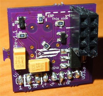
The board were shipped to me and received. I did my best soldering the components to the board. I made big errors on the silk screen. But important connections seems to be ok.

I soldered the components to the board as best as I could. and this how it looks like.

imageimage


Results:

I am sending signals from an Arduino to the ESP8266 board and it seems to be receiving them ok. However it is not consistent when receiving communication from the ESP8266 back to the Arduino. My guess is faulty soldering on one of the transistors, but have not tested.


My Errors (for now):

1. Error in silk screen ( Vin is Vout, GND is not ground, TX is RX... )

2. Solder pads should be bigger to allow hand soldering correctly. Specially on Tantalum capacitors, they cover the entire pad so soldering is pain.


There is the issue that I should have tested the design before ordering the pcb but that is part of the adventure. It is a risk I had to take and do not recommend but do not regret.


Possible fixes I would do to this.

1. Fix Silk Sreen

2. Bigger solder pads

3. Change bottom usb connector to be micro usb.

3. Add a mounting hole if space available.

4. Do similar board for the ESP8266-03 board.

5. Add level shifting to digital IOs to make them 5v tolerant also.

6. Add smd switch in the bottom for firmware update mode.


There is so much to do with the board without actually making it bigger. I love adding features but is hard to do in so limited space.

  • Sign in to reply

Top Comments

  • scargill
    scargill over 10 years ago +1
    Very nice INDEED... yes, the BIGGEST headache using these boards is the damned 3v3 interface - absolutely everything of mine is 5v based (Arduinos,custom boards using the 1284 chip etc). That looks neat…
  • gadget.iom
    gadget.iom over 9 years ago in reply to Former Member

    Elsie Zhou wrote:


    ok, this is detailed enough

    Good

    • Cancel
    • Vote Up 0 Vote Down
    • Sign in to reply
    • More
    • Cancel
  • Former Member
    Former Member over 9 years ago

    ok, this is detailed enough

    • Cancel
    • Vote Up 0 Vote Down
    • Sign in to reply
    • More
    • Cancel
  • camuyano
    camuyano over 10 years ago in reply to deepankarmaithani

    The design is here. I did two other tries by using a usb to serial converter. There has been some issues on making it work and those project are now in low priority mode for now. But this Wifico board seems to do what it is was intended to do. There is an error on the silk screen. If you go into eagle, check the silk screen of the pinout and the actual connections. I dont remember if I fixed them and uploaded the fix. Also the bidirectional level shifter I think you can get around with only the RX, but there is not much cost on adding the other one. My design was made so it can be ordered on OSHPark so it is $5 (shipping free) for 3 PCBs.

    https://github.com/soynerdito/WifIco

    • Cancel
    • Vote Up 0 Vote Down
    • Sign in to reply
    • More
    • Cancel
  • deepankarmaithani
    deepankarmaithani over 10 years ago

    @javier Can you share your eagle design files,if i am not asking for too much? i was also working on this and there are no boards available so far and as u said it is a ppain to work with these non breadboard friendly boards on a protoboard. @peter Scargill  hello sir i have seen your videos too.Nice job.

    • Cancel
    • Vote Up 0 Vote Down
    • Sign in to reply
    • More
    • Cancel
  • Former Member
    Former Member over 10 years ago

    That is a great board for experimentation, to create a stand alone project though you need something like the board at ByVac (http://www.byvac.com/bv3/index.php?route=product/product&product_id=172http://) This will give lots of I/O plus there is a very easy Rapid Application Development system on board which is interactive so no need to get out the old fashioned Arduino with its write,compile,download and see method of development.

    • Cancel
    • Vote Up 0 Vote Down
    • Sign in to reply
    • More
    • Cancel
>
element14 Community

element14 is the first online community specifically for engineers. Connect with your peers and get expert answers to your questions.

  • Members
  • Learn
  • Technologies
  • Challenges & Projects
  • Products
  • Store
  • About Us
  • Feedback & Support
  • FAQs
  • Terms of Use
  • Privacy Policy
  • Legal and Copyright Notices
  • Sitemap
  • Cookies

An Avnet Company © 2025 Premier Farnell Limited. All Rights Reserved.

Premier Farnell Ltd, registered in England and Wales (no 00876412), registered office: Farnell House, Forge Lane, Leeds LS12 2NE.

ICP 备案号 10220084.

Follow element14

  • X
  • Facebook
  • linkedin
  • YouTube