


Introduction
This blog post relates to a simple digital signal processing setup, as demonstrated in this two-minute video. No actual coding is needed for these experiments, everything is drag-and-drop, and only a few jumper wires need connecting to off-the-shelf boards.
What is DSP?
A huge part of electronics, and software in general too, is all concerned about manipulating signals. Signals could be speech, music, the temperature in a room, vibrations and so on. Often these analog signals are filtered or amplified or modified using resistors, capacitors, inductors and op-amps for instance. Another way is to convert the analog signal into digital (using an Analog to Digital Converter or ADC) and then perform mathematic operations on the stream of binary data, and then convert back to analog using DACs. One way to do this could be to attach an ADC and a DAC to a microprocessor or microcontroller and write code to perform the mathematical operations. Many processors contain built-in hardware acceleration features to make this digital signal processing more efficient. Another way could be to use a dedicated digital signal processing (DSP) chip. Such chips can be very similar to typical microprocessors or microcontrollers but have memory and functionality organized in a way that helps perform popular mathematics operations. One of the key operations is the Discrete Fourier Transform (DFT), which can be achieved by taking a chunk of the sequence of values, multiplying with specific values, and adding the results. It is broken down into many of these Multiply-Accumulate (accumulate just means to add) or MAC operations. A DSP chip, and any hardware accelerators for DSP in processors, will have digital logic to extract data from memory busses and perform MAC operations at high speed. Without this special hardware acceleration, it could take a hundred times as long (or longer) to do it in software using conventional microprocessor central processing units (CPUs).
Programming such DSP functionality partially involves being able to direct incoming data streams, or RAM or Flash tables of data, into the hardware accelerators to perform the MAC operations. Any other operations required to perform the end algorithm to meet the end requirement will also need to be coded. A typical end requirement could be as simple as amplification (in other words multiplying each sample by a fixed value) or as complex as audio compression (this could involve performing Fourier transform operations and storing the results efficiently in memory). Since hardware accelerators can be used to perform multiple operations simultaneously, expressing that in a normal programming language like C can become difficult. Some developers would learn the assembly language for the DSP chip and code with that as a result.
Another approach to the programming dilemma is to abstract it all and allow the programmer to use a blocks-based system to describe the flow of data and the operations that should be performed. It is a complex thing to do, but Analog Devices has managed to create software called Sigma Studio which will do exactly that. It can be considered to be a tool that allows coding using blocks, and the result is compiled into an executable binary file that can be programmed into Analog Devices DSP chips. This blog post describes how to do that. I'm just a beginner with such DSP chips, so this blog post merely describes how to get started, and to use Sigma Studio to design and program one audio effect.

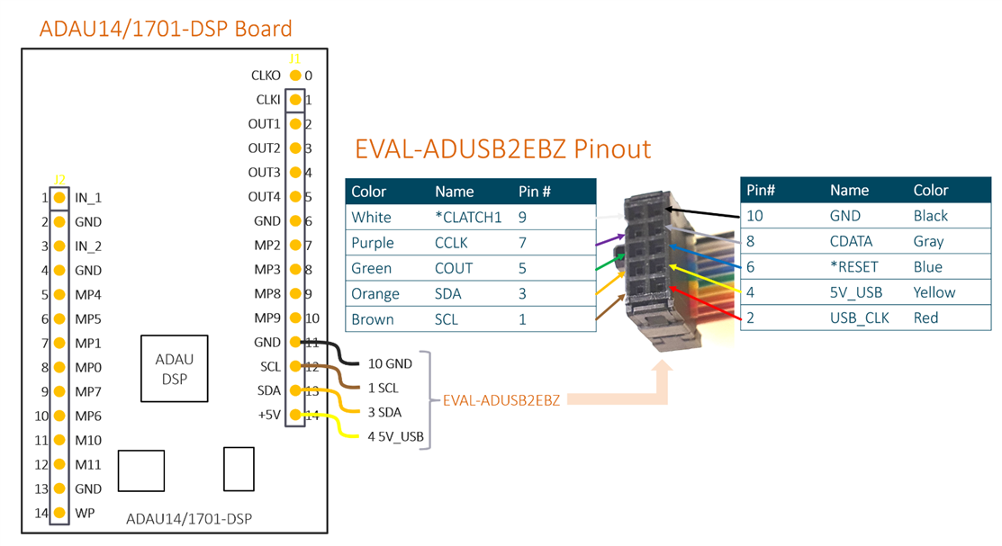
I used this equipment (the diagram below shows how it will be all connected):
- ADAU14/1701-DSP board from Aliexpress
- EVAL-ADUSB2EBZEVAL-ADUSB2EBZ programmer board
- Two 3.5mm audio jack plug connectors
- Audio source (for example a mobile phone with 3.5mm jack socket)
- Audio amplifier/speaker (I used a low-cost portable powered speaker)
- PC running Windows 10 (the software only supports Windows 7 and Windows 10, although it should be possible to use a virtual machine if (say) Linux or Mac is being used, but I have not tested this).
Installing the Software
From the Analog Devices website, I downloaded SigmaStudio Automotive and Generic Release SigmaStudio 64 Bit-OS Rev 4.6.
Install it, clicking through to install with the default settings and any drivers.
USBI Board ( EVAL-ADUSB2EBZEVAL-ADUSB2EBZ )
The manufacturer-recommended programmer for the DSP chips is the EVAL-ADUSB2EBZEVAL-ADUSB2EBZ board (also known as USBi Board). It is however $100. On the Internet there are suggestions about how to use a $15 board containing a Cypress chip, however, to use it, at least on Windows 10 is difficult because it entails disabling secure boot or other procedures, to get around an incorrect driver signature. I was unwilling to do that, so ended up deciding to pay for the manufacturer's tool. Another possibility which I have not tried is to obtain a clone of the USBi device from Aliexpress; that costs about $35.
Anyway, the official programmer has quite poor documentation, so I decided to document it here. It comes with a 10-way ribbon cable, and the pinout is shown below.
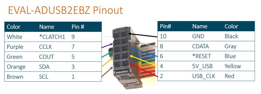
The programmer board has a tiny single DIP slide switch on the underside, to select either 3.3V or 1.8V logic. By default, mine was set to 3.3V and I left it there. Check your board and make sure it's set to 3.3V.
From the ribbon cable, the programmer needs four wires to be connected to the DSP board; SDA, SCL, +5V_USB, and GND. By doing this, the programmer will power the DSP board, and will control the I2C functions on the DSP board (the DSP chip and an EEPROM chip can be programmed this way).
The wiring summary is below, and this is enough to test the board to turn an LED on and off on the board, as will be discussed further below.
Turning an LED on and off
I found this useful tutorial which I pretty much followed with little changes. Basically, I ran SigmaStudio, created a New Project (select File -> New Project), and dragged USBi, ADAU1401 and E2Prom objects onto the Hardware Configuration pane, and connected them up as shown in the screenshot below. The main pane here is called Hardware Configuration and it contains several tabs at the bottom. At the top of the pane, you can see that there is also a Schematic pane, but that is not currently selected.

By default the Config tab is visible in the Hardware pane. I clicked on the 'IC1 – 170x\140x Register Control' tab and set MP2 to Output GPIO.

Next, I went back to the Config tab, and then I plugged in the USB connection to the programmer board and various LEDs on the programmer board lit up, eventually settling to red and yellow LEDs lit.
Looking at SigmaStudio, the USBi symbol that had been previously dragged into the pane had changed from red to green, indicating that the programmer had been detected.

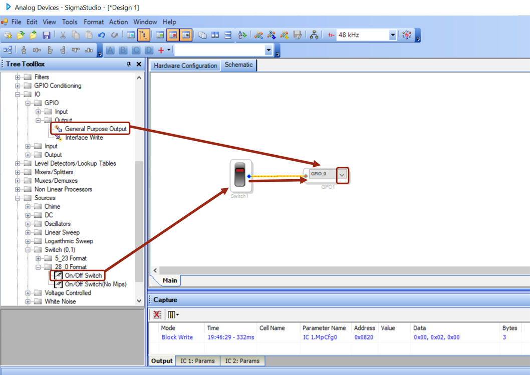
Incidentally an LED on the DSP board was blinking; I think it has a default program to do that perhaps. Anyway, I next clicked on the Schematic pane and dragged a switch and a General Purpose Output object onto the pane and connected them together. The screenshot below shows what to drag and connect. The GPO1 object that was dragged has a drop-down, and I used that to change it from GPIO_0 to GPIO_2.
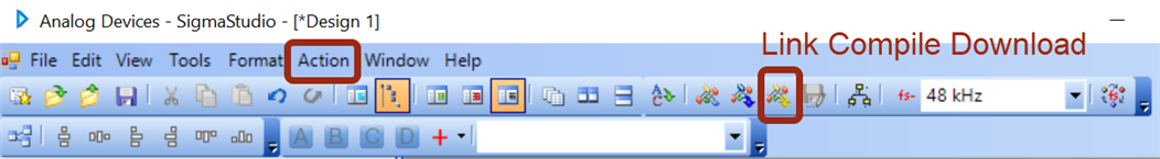
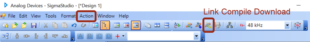
There is a 'Link Compile Download' button in the top toolbar in SigmaStudio (you can also find it in the Action menu, or you can just press F7). When I pressed it, the LED on the DSP board stopped blinking. Now, I could control it by clicking on the top or bottom part of the Switch object in the Schematic pane, as if I was really pressing on the top or bottom part of a physical rocker switch!
To make the code persistent so that it will run automatically after a reboot, you can write it to the EEPROM that is on the DSP board. That will be explored some other time.
A Simple Audio Effect
For this experiment, an audio source and output (audio amplifier connected to a speaker) are required. Connect up as shown below. Note that there are subtle variations of the ADAU14/1701-DSP board, so check carefully that the pinouts are the same, otherwise modify the connections accordingly. In particular, one variant of the board has slightly different pin numbering around header J1 pins 0-6, and around J2 pins 9-10. The diagram below shows the pinout for a board purchased recently (June 2021) so perhaps the older variants are no longer available.

I used a mobile phone with 3.5mm jack as the audio source, to play music. For the output, I used a portable amplified speaker.
Start up Sigma Studio, and then as before follow these steps:
- Create a new project (File->New Project)
- Drag USBi, ADAU1401 and E2Prom objects onto the main Hardware Configuration pane
- Drag connection lines between the USBi object to the ADAU1401 and E2Prom
Next, click on the Schematic pane as shown below, and drag three items as shown in the screenshot below, and connect them up by dragging two connections between them as shown too:

Plug in the programmer into your PC USB port, and in the Hardware Configuration pane you'll see that USB is green. Click back on the Schematic pane now since you'll be using that again soon.
Now click on the Link Compile Download icon as before (or find it in the Action menu, or just press F7):
You should hear music egressing out of the speaker. If you don't, then it's most likely because the volume on the mobile phone needs to be set to quite loud. I had to crank it up to almost max volume.
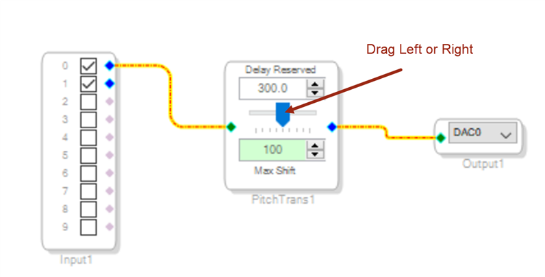
Now, to make use of the effect, in the Schematic Pane, drag the blue slider left or right. Notice the change in the audio : )
There is functionality in SigmaStudio to connect actual buttons or rotary encoders to manipulate functionality too, but I have not explored this so far.
Summary
This short blog post contains my initial findings on how easy it can be to get going with DSP chips. Although it was used to demonstrate just a single audio effect, of course, the possibilities are endless (and it doesn't need to be processing audio either). Although I'm a beginner with such devices, I hope to make more use of them.
Thanks for reading!


