


Introduction
HYDRA, named after the multi-headed monster, is a miniaturized general purpose electronic engineering tool with several bits of functionality.
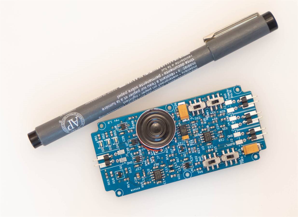
For instance an audio amplifier and an LED can allow for some quite extensive debugging for hobby circuits. When oscilloscopes were expensive such hardware debugging methods were popular. I wanted to build a test audio amplifier for the lab, and this project was the result. The full circuit diagram and PCB files are available (attached to this blog post).

HYDRA has these main areas of functionality:
- Fixed Sine Tone Generator; ~500Hz, amplitude is switch selectable 100mVp-p or 1Vp-p
- Logic Pulse Generator; frequency is switch selectable ~500Hz or ~2Hz and the output can be optionally gated with a logic ‘1’ input
- Audio Amplifier with built-in speaker; volume is switch selectable to low or high. It can be used to listen to signals in a circuit
- Three LED Voltage Level Indicator (can be used as a logic probe); Green=logic ‘0’, Yellow=logic ‘1’, Red=Overload
- Audio alert on voltage level (can be used as a logic probe); low tone=logic ‘0’, high tone=logic ‘1’or higher and the two tones can be separately enabled or disabled using two switches
All of these various bits of functionality are enabled/disabled using four on-board slide-switches.
HYDRA can be powered from the circuit-under-test or an external battery or power supply could be used. It typically needs a 3.3V supply although anything from 2.7-5.5V will work too. The LED voltage level indicator will show 3.3V logic levels when powered from a 3.3V supply.
The project uses very low cost, large surface mount components that were deliberately chosen to make this an easy project for beginners.
How it works
This project can be broken down into three main areas that are connected/combined or isolated using switches; the tone generators, the voltage level sensing circuit and the audio amplifier.
The tone generators use two op amps per tone. The first op amp generates a square wave and the second op amp forms a low-pass filter to remove harmonics to leave behind a (crude) sine wave. Two tones generators are on the PCB and one of them can be changed a 2Hz square wave by switching in a capacitor.
Since it can get tiring listening to tones despite a ‘pleasing’ pair of tones being chosen (A# and C#) it is possible to individually switch them off or to select a lower volume by appropriate switch combinations.
The audio amplifier is a straightforward headphone amplifier circuit (actually a stereo amplifier circuit but one channel is unused) permanently wired to a small speaker. The input can come from either (or both) tone generators and an external audio source. All three inputs are mixed together but each tone input can be optionally switched off.

The voltage level sensing is done using comparators and a potential divider ladder which is set to the approximate reference thresholds for detecting voltages close to zero volts (i.e. logic ‘0’), voltages higher than 2V (logic ‘1’) and overvoltage (voltages higher than about 4V). With the voltage sensing probe connection left unconnected it internally floats to an intermediate voltage so that both the low tone and the high tone are switched off.
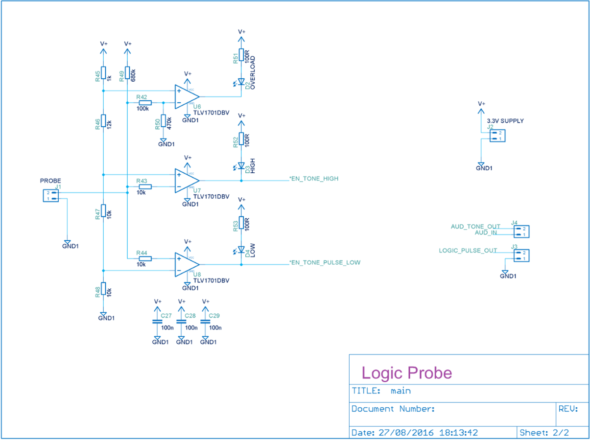
Please note that the levels are only approximate but generally usable. This project is not a replacement for a multimeter or an oscilloscope.
Building it
Order a PCB using the Gerber files attached to this post (the selected case is extremely thin and a 0.8mm thick PCB is needed so that everything fits; if you’re not using the case a normal 1.6mm thickness PCB is fine). The components list is shown below. Most surface mount resistors and capacitors are so low cost that it makes sense to buy 50 or 100 of them and keep the remainder for future projects.
When the PCB arrives start soldering the smallest components first and leave the switches and connectors until the end.

The connector pads are optionally designed for a springy lever type connection but in the end I just used single-in-line (SIL) pins; there are holes for this on the board. Screw terminals can also fit.
The underside has the connector pinouts marked and the official project logo.

How to solder
Everyone has their own variations but one typical prototyping technique that works well is to hold the component in position with tweezers and then apply very thin solder and the iron. The tweezers and solder can be held in one hand with some practice, and the iron in the other hand. By rocking the fingers the solder can be made to touch the join area while soldering.
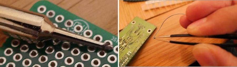
For this technique to work, the soldering iron tip needs to be small (1-2mm) and the solder needs to be thin. A temperature controlled iron with about 50W of power or more would be suitable.
Once one terminal has been soldered down, the tweezers can be removed and the remainder terminals can continue to be soldered. A small bit of flux on the PCB pads is useful if the pads or components are slightly oxidised.
If there are any shorts then they can be removed with thin de-soldering braid. The board can be cleaned up afterwards with either flux remover or IPA wipes.
Final assembly
The speaker is glued into position (or double-sided adhesive tape used) only after it is confirmed that everything works; some of the components will be difficult to access after the speaker is attached.
If desired a pointy metal rod could be used for the voltage level (logic probe) input.
To test the board, it was initially powered up from a 3.3V supply with a 100 ohm resistor connected in series. Once it was confirmed that the circuit was behaving as expected (LEDs functioning in the probe mode, and tones being generated when expected) then the resistor was removed.
Using it
Hydra is powered from 3.3V which can come from the circuit under test. The supply voltage can actually be anything from 2.7V to 5.5V but it does affect the thresholds used for the voltage level sensing. With a 5V supply, the high level is detected at 3V instead of 2V, and the overvoltage level is detected at 5.9V instead of 3.9V. These are still generally usable however there are different logic families and it will not be entirely compatible in all conditions with all circuits. It is a compromise between accuracy, usability, and circuit simplicity.
For power small batteries are a possibility because the power requirements are low so two AA or AAA alkaline cells should provide many years of use. There is no power switch on the PCB so one would need to be externally wired in series with the battery.
The easiest way to operate Hydra is to just experiment with the switch combinations until it does what you want!
Note: After building and testing this project, everything functions as expected however the sine tone (intended to be just an approximate sine wave) was noticed to clip; this results in some harmonics so the sine output is quite crude, worse than I wanted. I think it doesn’t detract from the uses for the project but if I was re-doing it I would seek to improve the design in that area.
Summary
Although it functions and HYDRA revision 1.0 is very usable, if I was designing a revision 2 board I would also remove the springy connector locations to free up some space. And I would incorporate a battery and power switch and a pointy probe. But nevertheless for general use revision 1.0 works fine.
This was just a quick blog post on a quick project; if people do build it, it would be interesting to hear about what uses they find for it.
Parts List
Resistors
| Part | Value | Size |
| R18, R27, R36, R37, R42 | 100k100k | 0603 |
| R13, R14, R15, R21, R22, R23, R43, R44, R47, R48 | 10k10k | 0603 |
| R19, R26, R28, R29, R31, R32, R34, R35, R40, R45 | 1k1k | 0603 |
| R51, R52, R53 | 100R100R | 0603 |
| R41 | 220R220R | 0603 |
| R33 | 110R110R | 0603 |
| R46 | 12k12k | 0603 |
| R30, R38 | 15k15k | 0603 |
| R24, R25 | 20k20k | 0603 |
| R39 | 22k22k | 0603 |
| R16, R17 | 24k24k | 0603 |
| R12 | 150k150k | 0603 |
| R20 | 130k130k | 0603 |
| R50 | 470k470k | 0603 |
| R49 | 680k680k | 0603 |
Capacitors
| Part | Value | Size |
| C10, C12, C13, C14, C15, C17, C18, C19 | 10n10n | 0603 |
| C11, C16, C22, C24, C27, C28, C29 | 100n100n | 0603 |
| C20, C26 | 2.2u2.2u | 0805 |
| C23 | 0.33u0.33u | TANT-A |
| C21, C25 | 100u 10V100u 10V | TANT-D |
LEDs, Transistors and ICs
| Part | Value | Size |
| D2 | LED_OL_REDLED_OL_RED | 0603 |
| D3 | LED_HIGH_YELLED_HIGH_YEL | 0603 |
| D4 | LED_LOW_GRNLED_LOW_GRN | 0603 |
| Q1, Q2 | BSS138 N-MOSFETBSS138 N-MOSFET | SOT23 |
| U2, U3 | LMV358 DUALOPAMPLMV358 DUALOPAMP | SO8 |
| U4 | LM4808 AUDIO AMPLM4808 AUDIO AMP | SO8 |
| U5 | LMV321 OP AMPLMV321 OP AMP | SOT23-5 |
| U6, U7, U8 | TLV1701DBV COMPTLV1701DBV COMP | SOT23-5 |
Switches, Connectors and Speaker
| Part | Value | Size |
| SW1 | 500Hz/2Hz | JS202011SCQNJS202011SCQN |
| SW2 | VOL | JS202011SCQNJS202011SCQN |
| SW3 | TONE_LOW/PULSE_EN | JS202011SCQNJS202011SCQN |
| SW4 | TONE_HIGH_EN | JS202011SCQNJS202011SCQN |
| J1 | PROBE | SIL Header RASIL Header RA |
| J2 | 3.3V SUPPLY | SIL Header RASIL Header RA |
| J3 | LOGIC PULSE | SIL Header RASIL Header RA |
| J4 | TONE/AUDIO | SIL Header RASIL Header RA |
| J7 | SPEAKER | KDMG20008KDMG20008 |

