element14 Community
element14 Community
    Register Log In
  • Site
  • Search
  • Log In Register
  • Community Hub
    Community Hub
    • What's New on element14
    • Feedback and Support
    • Benefits of Membership
    • Personal Blogs
    • Members Area
    • Achievement Levels
  • Learn
    Learn
    • Ask an Expert
    • eBooks
    • element14 presents
    • Learning Center
    • Tech Spotlight
    • STEM Academy
    • Webinars, Training and Events
    • Learning Groups
  • Technologies
    Technologies
    • 3D Printing
    • FPGA
    • Industrial Automation
    • Internet of Things
    • Power & Energy
    • Sensors
    • Technology Groups
  • Challenges & Projects
    Challenges & Projects
    • Design Challenges
    • element14 presents Projects
    • Project14
    • Arduino Projects
    • Raspberry Pi Projects
    • Project Groups
  • Products
    Products
    • Arduino
    • Avnet Boards Community
    • Dev Tools
    • Manufacturers
    • Multicomp Pro
    • Product Groups
    • Raspberry Pi
    • RoadTests & Reviews
  • Store
    Store
    • Visit Your Store
    • Choose another store...
      • Europe
      •  Austria (German)
      •  Belgium (Dutch, French)
      •  Bulgaria (Bulgarian)
      •  Czech Republic (Czech)
      •  Denmark (Danish)
      •  Estonia (Estonian)
      •  Finland (Finnish)
      •  France (French)
      •  Germany (German)
      •  Hungary (Hungarian)
      •  Ireland
      •  Israel
      •  Italy (Italian)
      •  Latvia (Latvian)
      •  
      •  Lithuania (Lithuanian)
      •  Netherlands (Dutch)
      •  Norway (Norwegian)
      •  Poland (Polish)
      •  Portugal (Portuguese)
      •  Romania (Romanian)
      •  Russia (Russian)
      •  Slovakia (Slovak)
      •  Slovenia (Slovenian)
      •  Spain (Spanish)
      •  Sweden (Swedish)
      •  Switzerland(German, French)
      •  Turkey (Turkish)
      •  United Kingdom
      • Asia Pacific
      •  Australia
      •  China
      •  Hong Kong
      •  India
      •  Korea (Korean)
      •  Malaysia
      •  New Zealand
      •  Philippines
      •  Singapore
      •  Taiwan
      •  Thailand (Thai)
      • Americas
      •  Brazil (Portuguese)
      •  Canada
      •  Mexico (Spanish)
      •  United States
      Can't find the country/region you're looking for? Visit our export site or find a local distributor.
  • Translate
  • Profile
  • Settings
Open Source Hardware
  • Technologies
  • More
Open Source Hardware
Forum CNC Interface Board discussion
  • Blog
  • Forum
  • Documents
  • Events
  • Polls
  • Members
  • Mentions
  • Sub-Groups
  • Tags
  • More
  • Cancel
  • New
Join Open Source Hardware to participate - click to join for free!
Actions
  • Share
  • More
  • Cancel
Forum Thread Details
  • Replies 35 replies
  • Subscribers 310 subscribers
  • Views 6181 views
  • Users 0 members are here
  • linuxcnc
  • engraver
  • cnc
  • bbb
  • machinekit
  • BeagleBone Black
Related

CNC Interface Board discussion

shabaz
shabaz over 5 years ago

This is a thread to discuss ideas for controlling low-cost hardware (machines), for the purposes of cutting or engraving for example. It was created due to the interest in ralphjy project to assemble such a device.

There are several ways to do this, typically the 'brains' are a normal desktop or laptop PC, or a single board computer (SBC), and then there is some interface board, that then ultimately connects via high-power drivers, to the motors. There are some other bits of functionality too, like feedback (e.g. limit switches) for detecting end stops.


In terms of motors, in industry servomotors will be used, but for home use stepper motors are a lot more popular due to lower cost. For controlling the tool, a 'spindle motor' may be a brushless motor, or alternatively a brushed permanent magnet DC motor (i.e. BLDC or PMDC motor respectively).


The PC connection to the interface board can typically be a parallel interface, or USB. When using a SBC then its on-board general-purpose input/output (GPIO) can be used.


The BeagleBone Black (BBB) is worth considering I think, since it has been the first popular Linux product to be integrated into machines, providing functionality for 3D printers and small CNC machines. Commercial manufacturing products have been launched with the BeagleBone inside, such as the PocketCNC. There are also third party add-on boards that act as interface boards (and some that integrate motor drivers too). The BBB is old now, but there is a BeagleBone-AI that could in future be used as an upgrade.


Partly the reason the BBB has been useful is because it contains some programmable real-time units (PRU) internally, and they can override some GPIO pins, for direct control without needing to go through the Linux system. So, the Linux system can push code to execute on the PRU, and the PRU will control the pins. This means high speeds, and no unexpected delays or jitter, since the PRUs are simpler devices that do not run an operating system that could have a task preempted.


To control the interface cards, PCs have a wider choice of software, and popular choices are Mach 3 and LinuxCNC. For the BBB, the software all the boards seem to use is called Machinekit, which is a fork of LinuxCNC.


Using it for BBB is not documented well unfortunately. When I first started looking a while back, it was hard to tell which information works, and which information is old. I wanted to automate a simple XY table I'd bought.

However, there is a fairly recent blog article with useful pointers.  It too discusses that information is spread out.


It would be nice to develop hardware (or to at least consider it first), and any software or configurations, documented, that would allow low-cost control of machines, and to bound it a little, to only consider home-grade machines using stepper motors, not servomotors. I think there is value in a new open source design, to collect up the wisdom of the various CNC users here, so we can all have low-cost home robots to make things for us!

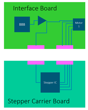
After some initial thinking, these sketches were a couple of ideas: They are based around the thought that the BBB could be a plug-on daughter card on a larger interface board, that uses something like RJ45-style connectors (because it would be nice to use off-the-shelf cables where possible, to reduce wiring effort, otherwise there are a lot of wires to connect).

image


image

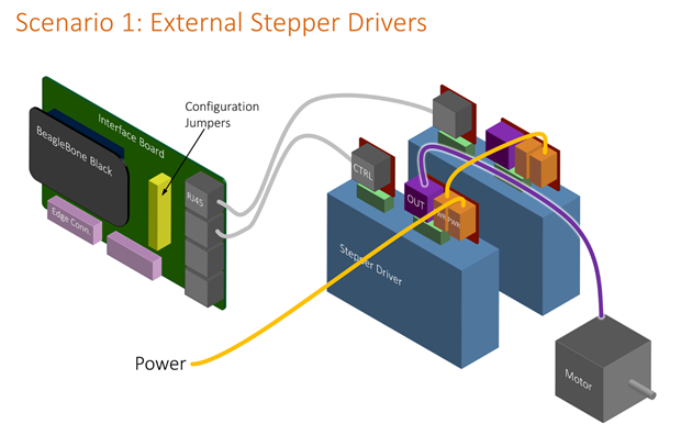
After some further discussions with balearicdynamics, it was suggested that scenario 1 could be more practical since it can handle more motors (low power and high power). I too like that idea, since it is one less board to make.

Edge connectors or some other connection location could still be left on the board, for those who do want to have a custom board for add-ons (e.g. to control a 3D printer instead, where they may need outputs for say a heater).


More input to any of this, including the practicality of it all, and board design (physical as well as functionality), and connector choices, is welcome. Meanwhile, I've been looking at the existing boards that are supported by Machinekit, to see what pins they use of the BBB, and why. I'll have to install Machinekit to better understand it. So far, I've looked at boards (or Machinekit configs) called CRAMPS, Replicape, and BeBoPr-Bridge and all use different pin mappings. I need to figure out which of these configs are using the PRU, and if so, which pins to allocate for that. I like the CRAMPS pin mapping so far, because it avoids eMMC and HDMI clashes (the BBB has these brought out to its connectors, and some interface boards tend to use these, which rules out using eMMC or HDMI as a result).


The pin mappings are in text files, but not easy to compare, so I've put them in a spreadsheet, I'll attach that as soon as it is complete.

The pin mapping text files are: CRAMPS.hal,  replicape.hal, BeBoPr-Bridge.hal  (I'll look at a few more too, and put them in the spreadsheet).

The mappings are numbers like 817, which means header P8 on the BBB, pin number 17.


EDIT: I'd hoped to daisy-chain the supplies, but looking at the user docs of a random one, it recommends against this practice:

image

So, the in/out connectors may not be a good idea, and a single power connector on each motor driver could be preferred.

I'm still looking for a suitable connector, but thinking it may as well be another RJ45-style, since I cannot think of another high power cheap alternative. Ethernet will carry lots of current safely, if wires are paralleled. There is the risk of accidentally plugging it into the wrong socket, but they could be color coded.

  • Sign in to reply
  • Cancel

Top Replies

  • Jan Cumps
    Jan Cumps over 5 years ago +7
    shabaz wrote: ... some programmable real-time units (PRU) internally, and they can override some GPIO pins, for direct control without needing to go through the Linux system. So, the Linux system can push…
  • Jan Cumps
    Jan Cumps over 5 years ago in reply to genebren +6
    ... another good reason to use a proper stepper driver is that it generates stepper friendly currents. A half bridge design, controlled by a pulse signal, will try (and succeed) to run the motor with square…
  • balearicdynamics
    balearicdynamics over 5 years ago in reply to shabaz +5
    Good idea of opening a separate thread. Enrico
Parents
  • genebren
    genebren over 5 years ago

    I would agree that scenario 1 does make the most sense.  Running lower current signal from the interface board, out to the driver, is a good idea.  That could make it possible to locate the drive closer to the motor (including the possibility of mounting it directly to the motor), thus limiting the IR losses between the driver and motor.  I also like the ability to have a common driver interface (signaling), so that different drivers could be used to match the motor being used (stepper, DC, etc).


    As far as connectors go, I do like the possibility to use RJ45 style connectors, given the ease of making cables (inexpensive connectors, mass termination, etc.).  For wiring between the motor and driver, I would like a high current option.  I have used, with good results, Phoenix Contact connectors, on some of the products that I have worked on.  They can be a bit pricey, but they are easy and quick when making connections.  Here is one of the styles that I am currently using (listed for 8A):

    image


    The power distribution, direct to each motor, does make a lot of sense.  With the motors (and drivers?) potentially being place throughout an assembly (i.e. not necessary grouped together), the daisy chain power might be more difficult and could create excess cable length.  Direct connection also tends to be a little less noisy.


    Off to a good start.

    Gene

    • Cancel
    • Vote Up +4 Vote Down
    • Sign in to reply
    • Cancel
  • Jan Cumps
    Jan Cumps over 5 years ago in reply to genebren

    ... another good reason to use a proper stepper driver is that it generates stepper friendly currents. A half bridge design,  controlled by a pulse signal,  will try (and succeed) to run the motor with square waves. But that’s never going to result in an efficient and smooth running design.

    • Cancel
    • Vote Up +6 Vote Down
    • Sign in to reply
    • Cancel
  • balearicdynamics
    balearicdynamics over 5 years ago in reply to Jan Cumps

    That's the reason that in many devices a more serious stepper controller should be used?

    • Cancel
    • Vote Up +4 Vote Down
    • Sign in to reply
    • Cancel
  • Jan Cumps
    Jan Cumps over 5 years ago in reply to balearicdynamics

    A stepper controller (IC or board) takes away the complexity of driving the individual coils properly. They often include logic to handle microstepping, stalled motor detection and torque management.

    Even with these controllers, there is enough complexity left for the firmware programmer to design an algorithm/profile that properly and smoothly controls the motor.

    For a DIY project, designing that driver/power circuit may be part of the fun.

    • Cancel
    • Vote Up +3 Vote Down
    • Sign in to reply
    • Cancel
Reply
  • Jan Cumps
    Jan Cumps over 5 years ago in reply to balearicdynamics

    A stepper controller (IC or board) takes away the complexity of driving the individual coils properly. They often include logic to handle microstepping, stalled motor detection and torque management.

    Even with these controllers, there is enough complexity left for the firmware programmer to design an algorithm/profile that properly and smoothly controls the motor.

    For a DIY project, designing that driver/power circuit may be part of the fun.

    • Cancel
    • Vote Up +3 Vote Down
    • Sign in to reply
    • Cancel
Children
  • shabaz
    shabaz over 5 years ago in reply to Jan Cumps

    The scenario 2 board "stepper driver carrier board" was for things along the lines of off-the-shelf stepper controller IC boards, but could be any custom board design. Especially for the reason you say, that it could be fun for some people to develop that if they preferred that over the scenario 1 individual driver modules. It will be nice to have interest and challenge areas for those who want that - and also it is hard to predict all scenarios, so a second board could be used to offload things for the future too. I'll put some ribbon cable socket on the "Interface board", to allow passing the signals to a potential second board, and another ribbon cable (or the same one) to pass the outputs back onto the Interface board, so that the output connectors are only needed on the one board basically.

    Something like this (the diagram is only showing one motor):

    image

    In other words, the "Motor 1" connector in the diagram, optionally serves double-duty. In scenario 1, it carries low-level signals to the external individual driver modules. In scenario 2, it is directly connected to the stepper motors. But even that could be optional, i.e. if the Stepper Carrier Board is designed for higher current than 1.5A per pin (i.e. 3A if I can double them up for bipolar motors) then the stepper carrier board could use its own connectors, e.g. screw terminals.

    • Cancel
    • Vote Up +3 Vote Down
    • Sign in to reply
    • Cancel
element14 Community

element14 is the first online community specifically for engineers. Connect with your peers and get expert answers to your questions.

  • Members
  • Learn
  • Technologies
  • Challenges & Projects
  • Products
  • Store
  • About Us
  • Feedback & Support
  • FAQs
  • Terms of Use
  • Privacy Policy
  • Legal and Copyright Notices
  • Sitemap
  • Cookies

An Avnet Company © 2025 Premier Farnell Limited. All Rights Reserved.

Premier Farnell Ltd, registered in England and Wales (no 00876412), registered office: Farnell House, Forge Lane, Leeds LS12 2NE.

ICP 备案号 10220084.

Follow element14

  • X
  • Facebook
  • linkedin
  • YouTube