element14 Community
element14 Community
    Register Log In
  • Site
  • Search
  • Log In Register
  • About Us
  • Community Hub
    Community Hub
    • What's New on element14
    • Feedback and Support
    • Benefits of Membership
    • Personal Blogs
    • Members Area
    • Achievement Levels
  • Learn
    Learn
    • Ask an Expert
    • eBooks
    • element14 presents
    • Learning Center
    • Tech Spotlight
    • STEM Academy
    • Webinars, Training and Events
    • Learning Groups
  • Technologies
    Technologies
    • 3D Printing
    • FPGA
    • Industrial Automation
    • Internet of Things
    • Power & Energy
    • Sensors
    • Technology Groups
  • Challenges & Projects
    Challenges & Projects
    • Design Challenges
    • element14 presents Projects
    • Project14
    • Arduino Projects
    • Raspberry Pi Projects
    • Project Groups
  • Products
    Products
    • Arduino
    • Avnet Boards Community
    • Dev Tools
    • Manufacturers
    • Multicomp Pro
    • Product Groups
    • Raspberry Pi
    • RoadTests & Reviews
  • Store
    Store
    • Visit Your Store
    • Choose another store...
      • Europe
      •  Austria (German)
      •  Belgium (Dutch, French)
      •  Bulgaria (Bulgarian)
      •  Czech Republic (Czech)
      •  Denmark (Danish)
      •  Estonia (Estonian)
      •  Finland (Finnish)
      •  France (French)
      •  Germany (German)
      •  Hungary (Hungarian)
      •  Ireland
      •  Israel
      •  Italy (Italian)
      •  Latvia (Latvian)
      •  
      •  Lithuania (Lithuanian)
      •  Netherlands (Dutch)
      •  Norway (Norwegian)
      •  Poland (Polish)
      •  Portugal (Portuguese)
      •  Romania (Romanian)
      •  Russia (Russian)
      •  Slovakia (Slovak)
      •  Slovenia (Slovenian)
      •  Spain (Spanish)
      •  Sweden (Swedish)
      •  Switzerland(German, French)
      •  Turkey (Turkish)
      •  United Kingdom
      • Asia Pacific
      •  Australia
      •  China
      •  Hong Kong
      •  India
      •  Korea (Korean)
      •  Malaysia
      •  New Zealand
      •  Philippines
      •  Singapore
      •  Taiwan
      •  Thailand (Thai)
      • Americas
      •  Brazil (Portuguese)
      •  Canada
      •  Mexico (Spanish)
      •  United States
      Can't find the country/region you're looking for? Visit our export site or find a local distributor.
  • Translate
  • Profile
  • Settings
Open Source Hardware
  • Technologies
  • More
Open Source Hardware
Forum Archaeology Resistivity Meter
  • Blog
  • Forum
  • Documents
  • Events
  • Polls
  • Members
  • Mentions
  • Sub-Groups
  • Tags
  • More
  • Cancel
  • New
Join Open Source Hardware to participate - click to join for free!
Actions
  • Share
  • More
  • Cancel
Forum Thread Details
  • Replies 332 replies
  • Subscribers 318 subscribers
  • Views 41557 views
  • Users 0 members are here
  • armp
  • archaeology resistivity meter
Related

Archaeology Resistivity Meter

kltm
kltm over 5 years ago

Hi I'm looking for ideas on an update to a resistivity meter for archaeology. The only published designs for diy were in 2 magazines. One was published in 1997 and the other in 2003. I have copies of both articles available. The reason behind this is the current high cost of available equipment, usually well beyond the reach of most archaeological groups. I've attached a basic block diagram. In the first magazine article the meter is very basic. It relied on the operators to write down the reading given as the survey was taken. Given that a normal survey grid is 20m x 20m and 1 reading is taken on every sq mtr there would be 400 readings to write down and then input into a program used to interpret the results. The later article is really an update to the first where a PIC has been added to record the readings. This again is prone to error, because eadings are taken manually by pressing a button.

I'm sure given the advances in electronics there must be better ways. 


image

  • Sign in to reply
  • Cancel

Top Replies

  • kltm
    kltm over 5 years ago in reply to michaelkellett +8
    Hi Michael This all sounds very interesting and encouraging. I see you have found the original article, the update is also on slideshare somewhere. I haven’t really thought much about cost, but as you…
  • michaelkellett
    michaelkellett over 5 years ago in reply to shabaz +7
    I can't live with that - I have to have symmetry The problem is that the Howland current pump doesn't constrain the voltage on the load at all when perfectly balanced - and my LTSpice model is unrealistically…
  • michaelkellett
    michaelkellett over 5 years ago in reply to michaelkellett +7
    AS promised - now for the phase sensitive detector. I couldn't easily model this in LTSpice, which is no great surprise because it needs multiplication and square roots. I used Simulink in MATLAB - which…
  • kltm
    kltm over 5 years ago in reply to shabaz

    Hi the probes don’t have to accurately aligned and they only need to make contact with the soil to take a reading. Some units take up to 20 readings in very quick succession and use average of this. You are correct in the method used to take the readings. The reason for the way it is done is laziness I guess. Most software, snuffler included, default to you starting in the south west corner of the grid and following the path you have drawn. Take readings 1 to 20 in row 1, then 20 to 1 in row 2 and so on.

    Ken

    • Cancel
    • Vote Up +3 Vote Down
    • Sign in to reply
    • Cancel
  • fmilburn
    fmilburn over 5 years ago

    Hi Ken,


    This is a very interesting project with great comments from Michael and Shabaz  I did not realize how low the soil resistance typically is.  Wikipedia gives the usual values to be from 10 up to 1000 (Ω-m) though sometimes higher.


    https://en.wikipedia.org/wiki/Soil_resistivity


    I am jumping ahead but assuming the typical user would be an enthusiast building this themselves as a diy project, open source.  If so, that would influence the choice of components, complexity and cost. Can you describe in a bit more detail your thoughts on that?


    Frank

    • Cancel
    • Vote Up +4 Vote Down
    • Sign in to reply
    • Cancel
  • kltm
    kltm over 5 years ago in reply to fmilburn

    Hi Frank

    yes as you have guessed I am an enthusiast building this for myself. I belong to an amateur archaeology group and we do have access to an RM Frobisher unit, although this is somewhat restricted. We quite often carry out surveys for other groups who don’t have access to equipment, mainly because of cost. The RM Frobisher unit is in the region of £3000 currently, and that’s about the going price for this sort of equipment. To my mind it’s heavily overpriced for what it is. You will see that the ball park cost figure put in on the article by Robert Beck is about £50.00, but that was 1997. I reckon on today’s prices I could put that at maybe £150 to £200. In use the RM Frobisher unit is fairly automatic. Place the probes at C1 R1 and it takes a reading and beeps to let you know, then lift the probes and place them in C1 R2 and so on up to 20. At the end of the row there is a double beep and you would swing round and put the probe in C2 R20 and come back down. At the end of the grid there is long beep, the unit then saves all the readings to sd card and shuts down. There is facility in the software to mark trees and other obstructions as dummy readings. The one criticism I have is the menus in the software are poorly written.
    The biggest shortfall in the current offerings is not having a live view. A simple on screen grid that would be populated as readings are taken. We currently have to post process usually that evening so you have no idea what you have until then. Sometimes on a grid you will have an area of interest. With these we would go back over that section, but increase the number of readings to every half a meter to improve the resolution. Easier to do when your all set up. Anyway this should hopefully give you a flavour of what’s required. The majority requirement will be in the software I guess, but I can play at that. I don’t think the electronics are that sophisticated, but they could certainly do with being updated.
    Ken

    • Cancel
    • Vote Up +5 Vote Down
    • Sign in to reply
    • Cancel
  • fmilburn
    fmilburn over 5 years ago in reply to kltm

    Thanks, that is helpful.  Actually a lot of things are even cheaper today.  What about surface mount parts, FPGAs, and PCB design.  Are you comfortable with those?  I like the simple diagram that Shabaz provided.  Are you comfortable programming microcontrollers in C/C++?  I think you said at one point you were comfortable with Python.  I would think a Pi or laptop could handle the user interface and post capture data analysis in essentially real time and display results as well as give instruction and take user input.  There are good mapping and plotting libraries for Python as an example.  But personally I would do the data capture on a microcontroller as Shabaz outlined.

    • Cancel
    • Vote Up +3 Vote Down
    • Sign in to reply
    • Cancel
  • kltm
    kltm over 5 years ago in reply to fmilburn

    Hi Frank I’ve never used surface mount, but I guess it shouldn’t be that difficult to use. I’ve done a wee bit of PCB design, but again very little. I mostly built circuits from PCB’s designed in magazine articles. FPGA’s are a new one on me, so I’ll have to do a bit of reading up on them. C/C++ I’ve not programmed in at all. My original programming goes back to the usual basic, Visual Basic and I did quite a bit of database programming a few years ago in Paradox and Delphi. I have used Python and I find that ok. although I’m no expert. Looks like I will have a lot of learning to do or maybe the project will be a little beyond me.
    Ken

    • Cancel
    • Vote Up +4 Vote Down
    • Sign in to reply
    • Cancel
  • michaelkellett
    michaelkellett over 5 years ago in reply to kltm

    Here are a couple of nice modern ADCs to think about:


    ADS1284 from TI, very high resolution, differential inputs, programmable gain, 130 dB signal to noise ratio, but about £47 each in ones.

    AD7195 from Analog devices, a mere 24 bit converter, might need input buffers but stiil with programmable gain and quite nice as well,  £11.73 each.


    If you are not used to soldering sm parts go for the AD7195.


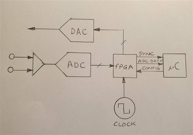
    Match it to an STM32F4xx processor, it is essential that the ADC sample rate be synchronised with the DAC used to generate the drive signal.

    A tiny FPGA might be helpful to do this.

    The ADCs say they have SPI interfaces but it can be very hard to get a good link with a uP and control sample rates - once again the tiny FPGA can save your bacon here.

    I would use a Lattice ICE40 series part, cheap and easy to code (for an FPGA) and low power.


    You'll notice that simple designs use square wave excitation - this is a bad idea - sine wave excitation doesn't have all those horrible harmonics to mix with intereference signals

    and leak back into the passband of your synchronous filter.

    The actual filtering can be realised entirely in software (that's why we want an ADC with huge dynamic range.)

    The power amplifier can be two op amps - pick the right ones and buffering might not be needed for 10mA drive current.

    A standard type op amp pair (running from +/- 15V rails) can produce about 20 V RMs which is quite good.


    The code on the micro will have to written in C (no support for anything else). I suggest you do only basic proecessing on the micro and have a serial port  whcih can connect it

    to a Windows laptop (if you want to use Snuffler) or an RPi ( or any Linux machine) if you mean to roll your own software.


    It's not hard to add a Bluetooth module for simple serial data transfer to phones or tablets.


    MK

    • Cancel
    • Vote Up +5 Vote Down
    • Sign in to reply
    • Cancel
  • kltm
    kltm over 5 years ago in reply to shabaz

    Hi Shabaz This looks interesting, I’ll have to do some reading up on FPGA’s as I have no experience of them at all. I think I can understand the rest of it though. Thank you for your time and effort, it’s very much appreciated.
    Ken

    • Cancel
    • Vote Up +4 Vote Down
    • Sign in to reply
    • Cancel
  • kltm
    kltm over 5 years ago in reply to michaelkellett

    Hi Michael I’ll take a look at these, I don’t have any experience with FPGA’s so I’ll have to try and get my head around them.
    Thank you for help and input, much appreciated.

    Ken

    • Cancel
    • Vote Up +4 Vote Down
    • Sign in to reply
    • Cancel
  • shabaz
    shabaz over 5 years ago in reply to kltm

    Hi Ken,


    A low-cost training board may be the ICE40HX1K-STICK-EVNICE40HX1K-STICK-EVN which contains the FPGA, memory for the bitstream, USB programming interface, a 12MHz clock source, a few LEDs and not much else.

    I've purchased that to self-learn that particular FPGA model too. It has solderable pins, and a socket, with easily enough pins for ADC, DAC and microcontroller interfacing.

    The only annoying thing about it is that it is quite a large board, and will snap off if hanging out the side of a PC/laptop, so a USB type A plug-to-socket cable could be useful too.


    I think the modified portion of the diagram ends up looking like this based on michaelkellett suggestions. The FPGA<->Microcontroller interface is only vaguely drawn, it needs designing. Ideally the FPGA needs to clock everything, so the microcontroller can sit waiting on an interrupt and read the ADC data. Some sync line would be used to indicate to the microcontroller that the DAC is about to start generating a new cycle of sine wave. The config lines would need to set up the rate at which the DAC and ADC operate, and start/stop the operation.

    image

    • Cancel
    • Vote Up +2 Vote Down
    • Sign in to reply
    • Cancel
  • fmilburn
    fmilburn over 5 years ago in reply to michaelkellett

    Michael,


    Thanks for highlighting the importance of synchronizing the DAC and ADC. It is something I have not had to worry much about before although the importance is clear in this application.  I did a quick search just now and as is sometimes the case there are a number of hits most of which are confusing, scant or not applicable. How would  you would approach it or is there a reference you can recommend?  Also since SPICE is showing up a lot recently on e14, is the excitation circuit one that would benefit from simulation first in SPICE?


    Frank

    • Cancel
    • Vote Up +4 Vote Down
    • Sign in to reply
    • Cancel
<>
element14 Community

element14 is the first online community specifically for engineers. Connect with your peers and get expert answers to your questions.

  • Members
  • Learn
  • Technologies
  • Challenges & Projects
  • Products
  • Store
  • About Us
  • Feedback & Support
  • FAQs
  • Terms of Use
  • Privacy Policy
  • Legal and Copyright Notices
  • Sitemap
  • Cookies

An Avnet Company © 2025 Premier Farnell Limited. All Rights Reserved.

Premier Farnell Ltd, registered in England and Wales (no 00876412), registered office: Farnell House, Forge Lane, Leeds LS12 2NE.

ICP 备案号 10220084.

Follow element14

  • X
  • Facebook
  • linkedin
  • YouTube