element14 Community
element14 Community
    Register Log In
  • Site
  • Search
  • Log In Register
  • Community Hub
    Community Hub
    • What's New on element14
    • Feedback and Support
    • Benefits of Membership
    • Personal Blogs
    • Members Area
    • Achievement Levels
  • Learn
    Learn
    • Ask an Expert
    • eBooks
    • element14 presents
    • Learning Center
    • Tech Spotlight
    • STEM Academy
    • Webinars, Training and Events
    • Learning Groups
  • Technologies
    Technologies
    • 3D Printing
    • FPGA
    • Industrial Automation
    • Internet of Things
    • Power & Energy
    • Sensors
    • Technology Groups
  • Challenges & Projects
    Challenges & Projects
    • Design Challenges
    • element14 presents Projects
    • Project14
    • Arduino Projects
    • Raspberry Pi Projects
    • Project Groups
  • Products
    Products
    • Arduino
    • Avnet Boards Community
    • Dev Tools
    • Manufacturers
    • Multicomp Pro
    • Product Groups
    • Raspberry Pi
    • RoadTests & Reviews
  • Store
    Store
    • Visit Your Store
    • Choose another store...
      • Europe
      •  Austria (German)
      •  Belgium (Dutch, French)
      •  Bulgaria (Bulgarian)
      •  Czech Republic (Czech)
      •  Denmark (Danish)
      •  Estonia (Estonian)
      •  Finland (Finnish)
      •  France (French)
      •  Germany (German)
      •  Hungary (Hungarian)
      •  Ireland
      •  Israel
      •  Italy (Italian)
      •  Latvia (Latvian)
      •  
      •  Lithuania (Lithuanian)
      •  Netherlands (Dutch)
      •  Norway (Norwegian)
      •  Poland (Polish)
      •  Portugal (Portuguese)
      •  Romania (Romanian)
      •  Russia (Russian)
      •  Slovakia (Slovak)
      •  Slovenia (Slovenian)
      •  Spain (Spanish)
      •  Sweden (Swedish)
      •  Switzerland(German, French)
      •  Turkey (Turkish)
      •  United Kingdom
      • Asia Pacific
      •  Australia
      •  China
      •  Hong Kong
      •  India
      •  Korea (Korean)
      •  Malaysia
      •  New Zealand
      •  Philippines
      •  Singapore
      •  Taiwan
      •  Thailand (Thai)
      • Americas
      •  Brazil (Portuguese)
      •  Canada
      •  Mexico (Spanish)
      •  United States
      Can't find the country/region you're looking for? Visit our export site or find a local distributor.
  • Translate
  • Profile
  • Settings
Passive Components
  • Technologies
  • More
Passive Components
Forum What is the Purpose of Resistor R1 in this Circuit
  • Blog
  • Forum
  • Documents
  • Quiz
  • Events
  • Polls
  • Members
  • Mentions
  • Sub-Groups
  • Tags
  • More
  • Cancel
  • New
Join Passive Components to participate - click to join for free!
Actions
  • Share
  • More
  • Cancel
Forum Thread Details
  • State Suggested Answer
  • Replies 7 replies
  • Answers 6 answers
  • Subscribers 107 subscribers
  • Views 4089 views
  • Users 0 members are here
  • power_supply
Related

What is the Purpose of Resistor R1 in this Circuit

jw0752
jw0752 over 6 years ago

This last weekend I had to repair a simple circuit that was designed to turn a vacuum system on and off with the alternate push of a SPST momentary switch. Here is the circuit that I worked on.


image

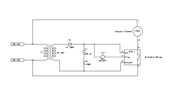
The problem turned out to be that the manufacturer had the C1 capacitor installed reversed polarity. Removal of the capacitor and replacement with  a new one in the proper polarity solved the problem.


My question concerns the 150 Ohm R! resistor as I have never seen a power supply with the negative lead of the filter capacitor held above ground. Can someone give me some information on what the designer's reason for the inclusion of R1 in this circuit might have been?


Thanks John

  • Sign in to reply
  • Cancel

Top Replies

  • dougw
    dougw over 6 years ago +6 suggested
    Perhaps it is to limit inrush current and avoid stressing the diode or upstream fuses? It could also be to limit discharge current when power is removed (to avoid stressing the module's protection diodes…
  • jw0752
    jw0752 over 6 years ago +5
    Here is perhaps a better image of the schematic: John
  • shabaz
    shabaz over 6 years ago in reply to jw0752 +5 suggested
    Hi John! I'm not sure, but maybe the transformer is very small and as Doug says, it could be to reduce high current draw briefly. Those types of relays are very cool.. I think they maybe referred as step…
  • jw0752
    0 jw0752 over 6 years ago

    Here is perhaps a better image of the schematic:


    image


    John

    • Cancel
    • Vote Up +5 Vote Down
    • Sign in to reply
    • Verify Answer
    • Cancel
  • dougw
    0 dougw over 6 years ago

    Perhaps it is to limit inrush current and avoid stressing the diode or upstream fuses?

    It could also be to limit discharge current when power is removed (to avoid stressing the module's protection diodes), but that would only be an issue if the button was pushed at the time when power was removed.

    • Cancel
    • Vote Up +6 Vote Down
    • Sign in to reply
    • Verify Answer
    • Reject Answer
    • Cancel
  • shabaz
    0 shabaz over 6 years ago in reply to jw0752

    Hi John!


    I'm not sure, but maybe the transformer is very small and as Doug says, it could be to reduce high current draw briefly.

    Those types of relays are very cool.. I think they maybe referred as step relays? I used a similar circuit to control the waste disposer, using a small 12V supply and a push-switch.. it's been functioning for 10 years.

    • Cancel
    • Vote Up +5 Vote Down
    • Sign in to reply
    • Verify Answer
    • Reject Answer
    • Cancel
  • gecoz
    0 gecoz over 6 years ago

    Hi John,


    I think the meaning of R1 is to reduce the power consumption of the relay once the contacts are triggered closed. The relay coil will have a defined operating current, needed to switch it to close, but once the contacts are closed, the current required by the coil to keep the relay contacts closed is normally sensibly lower than the operating current. Adding R1 will reduce the current flowing into the coil, thus reducing power consumption.


    There is a drawback though, but in your case I think can be ignored: adding R1 in series to C1 will make the capacitor time constant longer, hence limiting the switching speed of the relay.


    Fabio

    • Cancel
    • Vote Up +5 Vote Down
    • Sign in to reply
    • Verify Answer
    • Reject Answer
    • Cancel
  • DAB
    0 DAB over 6 years ago in reply to jw0752

    Hi John,


    I agree with the others. R1 would limit the initial current draw caused by the capacitor.

    Depending upon the type of capacitor, some electrolytic insulators break down during high current changes over small periods of time.

    It also might prevent parasitic oscillations between the transformer and the capacitor.


    DAB

    • Cancel
    • Vote Up +4 Vote Down
    • Sign in to reply
    • Verify Answer
    • Reject Answer
    • Cancel
  • jw0752
    0 jw0752 over 6 years ago in reply to jw0752

    Thanks for all the good ideas. I am sorry that I can't give much better detail particularly with respect to the relay module. I looked like a regular solid state relay module but in one corner there was a small mechanical relay mounted so it is some sort of hybrid. I have bread boarded the circuit and hooked up the scope and variable load so I could look at the effect of a range of loads on the quality of the DC voltage produced.


    image

    The transformer in this test is about the same size as the one I saw in the piece of equipment and so it should be at least an adequate power source for up to 250 mA  at 35 volts from my experience.


    image

    This first picture is of the output Vcc to ground with no load. We are seeing a 1.6 volt ripple on 34.8 volts DC.


    image

    In this picture we are looking at the same probe points but with a 10 mA load. Even a 10 mA load has degenerated the quality of the DC so that now we have 10.4 volts of ripple on the 34.4 Volt max.


    image


    This is the situation when there is a 50 mA load on the power supply. I suspect that the actual relay module draws no more than this current when it is active and holding the relay in. The power supply design at this load is only able to maintain a 6 volt DC offset.


    image

    Here we are looking at a 100 mA load and we see that the capacitor is making basically no contribution to supplying a DC voltage between cycles.


    image

    In this shot I have left the load at 100 mA and shorted out the 150 ohm resistor.


    From these tests it seems the best effect of the 150 Ohm resistor is to ruin the effectiveness of the capacitor to remove the ripple. From my experience with the type of relay module used in this unit there is no need or advantage to a poor quality DC supply but then I know very little in the big scheme of things. Based on the fact that the manufacturer assembled this unit with a reversed polarity capacitor it is entirely possible that the use of the resistor in this manner is also just a mistake. The unit is currently working as expected and my son doesn't want me to experiment with it now that it is working so I won't be able to take the experiment any further with the actual equipment.


    If anyone has experience with relay modules that work better with a poor quality DC supply it would be interesting to know why.


    Thanks dougw  ,shabaz ,  gecoz , and DAB  for helping me better understand the possible reasons for this design.


    John

    • Cancel
    • Vote Up +3 Vote Down
    • Sign in to reply
    • Verify Answer
    • Reject Answer
    • Cancel
  • Gough Lui
    0 Gough Lui over 6 years ago

    I'd side with inrush current limiting as the main reason - but maybe because the bistable relay may have some requirement regarding power-on rise time. A filter capacitor sitting over a halfwave rectifier would act like a dead short until it started charging, which would slow down the rise of Vcc when power is applied. The resistor will reduce inrush, reducing the rate at which the capacitor can charge and consequently discharge ... but also in turn would ensure Vcc rises faster although less stably.


    Otherwise, it could be because of some other behaviour regarding the bistable relay - perhaps upon power down or switching, it could result in a current spike that shortens the coil lifetime.


    - Gough

    • Cancel
    • Vote Up +3 Vote Down
    • Sign in to reply
    • Verify Answer
    • Reject Answer
    • Cancel
element14 Community

element14 is the first online community specifically for engineers. Connect with your peers and get expert answers to your questions.

  • Members
  • Learn
  • Technologies
  • Challenges & Projects
  • Products
  • Store
  • About Us
  • Feedback & Support
  • FAQs
  • Terms of Use
  • Privacy Policy
  • Legal and Copyright Notices
  • Sitemap
  • Cookies

An Avnet Company © 2025 Premier Farnell Limited. All Rights Reserved.

Premier Farnell Ltd, registered in England and Wales (no 00876412), registered office: Farnell House, Forge Lane, Leeds LS12 2NE.

ICP 备案号 10220084.

Follow element14

  • X
  • Facebook
  • linkedin
  • YouTube