element14 Community
element14 Community
    Register Log In
  • Site
  • Search
  • Log In Register
  • About Us
  • Community Hub
    Community Hub
    • What's New on element14
    • Feedback and Support
    • Benefits of Membership
    • Personal Blogs
    • Members Area
    • Achievement Levels
  • Learn
    Learn
    • Ask an Expert
    • eBooks
    • element14 presents
    • Learning Center
    • Tech Spotlight
    • STEM Academy
    • Webinars, Training and Events
    • Learning Groups
  • Technologies
    Technologies
    • 3D Printing
    • FPGA
    • Industrial Automation
    • Internet of Things
    • Power & Energy
    • Sensors
    • Technology Groups
  • Challenges & Projects
    Challenges & Projects
    • Design Challenges
    • element14 presents Projects
    • Project14
    • Arduino Projects
    • Raspberry Pi Projects
    • Project Groups
  • Products
    Products
    • Arduino
    • Avnet Boards Community
    • Dev Tools
    • Manufacturers
    • Multicomp Pro
    • Product Groups
    • Raspberry Pi
    • RoadTests & Reviews
  • Store
    Store
    • Visit Your Store
    • Choose another store...
      • Europe
      •  Austria (German)
      •  Belgium (Dutch, French)
      •  Bulgaria (Bulgarian)
      •  Czech Republic (Czech)
      •  Denmark (Danish)
      •  Estonia (Estonian)
      •  Finland (Finnish)
      •  France (French)
      •  Germany (German)
      •  Hungary (Hungarian)
      •  Ireland
      •  Israel
      •  Italy (Italian)
      •  Latvia (Latvian)
      •  
      •  Lithuania (Lithuanian)
      •  Netherlands (Dutch)
      •  Norway (Norwegian)
      •  Poland (Polish)
      •  Portugal (Portuguese)
      •  Romania (Romanian)
      •  Russia (Russian)
      •  Slovakia (Slovak)
      •  Slovenia (Slovenian)
      •  Spain (Spanish)
      •  Sweden (Swedish)
      •  Switzerland(German, French)
      •  Turkey (Turkish)
      •  United Kingdom
      • Asia Pacific
      •  Australia
      •  China
      •  Hong Kong
      •  India
      •  Korea (Korean)
      •  Malaysia
      •  New Zealand
      •  Philippines
      •  Singapore
      •  Taiwan
      •  Thailand (Thai)
      • Americas
      •  Brazil (Portuguese)
      •  Canada
      •  Mexico (Spanish)
      •  United States
      Can't find the country/region you're looking for? Visit our export site or find a local distributor.
  • Translate
  • Profile
  • Settings
Passive Components
  • Technologies
  • More
Passive Components
Forum Capacitor replacement
  • Blog
  • Forum
  • Documents
  • Quiz
  • Events
  • Polls
  • Members
  • Mentions
  • Sub-Groups
  • Tags
  • More
  • Cancel
  • New
Join Passive Components to participate - click to join for free!
Actions
  • Share
  • More
  • Cancel
Forum Thread Details
  • State Not Answered
  • Replies 26 replies
  • Subscribers 111 subscribers
  • Views 2789 views
  • Users 0 members are here
Related

Capacitor replacement

Former Member
Former Member over 10 years ago

Hello everyone!

I would need your help solving a little problem where I am not sure of the value of a capacitor that I need to replace.

I have never seen a capacitor like this one (yep, I'm a noob) so I searched online for some info and I though I could read it's value...the problem is that when I desoldered it from the board I noticed that on the other side it had other things written that, to my little knowledge, suggest a different value. Here are the pictures:


image

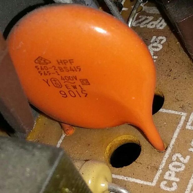
From this one I read that the precision is B, and the value is 4.1 uF with max 400v. The rest of the letters I have no idea what they mean.

image

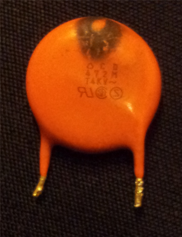
From this one I read that it is a 4,7 pF capacitor and the precision is M. The rest I do not understand.


What I would really like to know is what the actual value of the capacitor is and if possible, what the various things on both sides mean so that in the future I will be able to read them.

Thank you very much in advance

  • Sign in to reply
  • Cancel

Top Replies

  • mcb1
    mcb1 over 10 years ago +1
    Typing 472M into google gives you 26,700 replies or thereabouts. http://www.csgnetwork.com/capcodeinfo.html Your out by a long way ... Why are you thinking that is the problem.? I'd be looking more at…
  • mcb1
    mcb1 over 10 years ago in reply to Former Member +1
    Do you suggest replacing both the resistor and the capacitor at this point? Why? If the value of the capacitor (now you have it out) and the resistor are what they should be, then there is really no…
  • Former Member
    Former Member over 10 years ago in reply to mcb1 +1
    This is the main board from a 1970's/1980's tv...the power supply should be ok as it is a separate unit and I got it fixed a few months ago. The problem is that a few days ago the tv made a noise (like…
Parents
  • mcb1
    0 mcb1 over 10 years ago

    Typing 472M into google gives you 26,700 replies or thereabouts.

    http://www.csgnetwork.com/capcodeinfo.html


    Your out by a long way ...


    Why are you thinking that is the problem.?

    I'd be looking more at the component behind it, as it looks like either a scorch mark, or heat from a resistor.


    Mark

    • Cancel
    • Vote Up +1 Vote Down
    • Sign in to reply
    • Verify Answer
    • Cancel
  • Former Member
    0 Former Member over 10 years ago in reply to mcb1

    Ok, thank you very much! I though that was the problem because it is the only component that has any marks of damage, but it was right in front of a resistor so as you said it could probably be the heat from the resistor that made that mark. Do you suggest replacing both the resistor and the capacitor at this point?

    • Cancel
    • Vote Up 0 Vote Down
    • Sign in to reply
    • Verify Answer
    • Cancel
  • mcb1
    0 mcb1 over 10 years ago in reply to Former Member

    The only schematics I could find are for sale

    Keep searching and don't be afraid if some are in the former USSR as they seem to have lots of circuits/schematics.

    Try the forums for the TV as often they link to circuits.


    You had the supply repaired ... is the shop that did that able to help.?


    Just post back here.


    mark

    • Cancel
    • Vote Up 0 Vote Down
    • Sign in to reply
    • Verify Answer
    • Cancel
  • Former Member
    0 Former Member over 10 years ago in reply to mcb1

    Well the shop is probably capable of repairing the tv...the problem is that when I got the supply fixed I was very unhappy with the price. I know that many times people expect lower prices because they don't know how much time and effort it takes to repair this kind of stuff, but when I brought the TV I had already opened it and I told them where the problem was because it was very easy to spot. The only reason I brought the TV to them was because I didn't feel experienced enough to repair an old TV without risking to damage it. The point is, when I went back to get the TV, they charged me 80 bucks just to replace a capacitor. I don't find that to be fair since I know that it didn't take them much work...sorry for bothering you with this long story ahah

    • Cancel
    • Vote Up 0 Vote Down
    • Sign in to reply
    • Verify Answer
    • Cancel
  • Former Member
    0 Former Member over 10 years ago in reply to mcb1

    Ok, so, after some tinkering and testing I think I might have found the problem...but still, as I am used to, I have a doubt. Here is what I found.


    There is a transistor (pretty big one) that does not seem to have any visual damage on it but when I tested it I got the following results:

    pin 1 (positive lead multimeter) to pin 2 (negative lead multimeter) gave me the same resistance (almost, slightly higher) as pin 3 (positive lead multimeter) to pin 2 (negative lead multimeter) so I am thinking this is a PNP transistor,

    and since pin 1 to pin 3 gave me no resistance I am thinking the transistor is damaged.

    The "only" problem is that if I search for the code on the transistor (C3892A) on google I can only find datasheets for NPN transistors that go by that name.

    I am seriously confused right now. If you could give me some advice on this I would greatly appreciate it


    Here is the complete list of values from the multimeter:


    pin 1 (positive) to pin 2 (negative) reads 406;

    pin 1 (positive) to pin 3 (negative) reads 40 and beeps;

    pin 2 (positive) to pin 1 (negative) reads 1;

    pin 2 (positive) to pin 3 (negative) reads 1;

    pin 3 (positive) to pin 1 (negative) reads 40 and beeps;

    pin 3 (positive) to pin 2 (negative) reads 431;

    • Cancel
    • Vote Up 0 Vote Down
    • Sign in to reply
    • Verify Answer
    • Cancel
  • mcb1
    0 mcb1 over 10 years ago in reply to Former Member

    Franceso.

    Really quick reply from the airport.


    Try searching for a 2SC3892A.

    They usually drop the 2S to save room.


    Most transistors don;t show well unless you can bias the base with a finger or resistance to force it to conduct.

    Robert Peter Oakes


    Peter can you help in my absence.....image


    cheers

    Mark

    • Cancel
    • Vote Up 0 Vote Down
    • Sign in to reply
    • Verify Answer
    • Cancel
  • jw0752
    0 jw0752 over 10 years ago in reply to Former Member

    Hi Francesco,

    Your transistor number does cross to an NPN deflection / flyback transistor. How are you determining the polarity of your test leads on your Ohm meter? Several of my meters have the positive voltage on the black lead of the Ohm meter. Confusing but for whatever reason this is the way they were designed. Typically these transistors fail in a shorted condition. If you do not have a short between any of the leads it may not be the transistor.

    John

    • Cancel
    • Vote Up 0 Vote Down
    • Sign in to reply
    • Verify Answer
    • Cancel
  • Former Member
    0 Former Member over 10 years ago in reply to mcb1

    Ok, thank you very much...by adding the "2S" in front I was able to find a lot of information on the transistor!

    • Cancel
    • Vote Up 0 Vote Down
    • Sign in to reply
    • Verify Answer
    • Cancel
  • Former Member
    0 Former Member over 10 years ago in reply to jw0752

    The multimeter should be "regular" with red as positive and black as negative because all other readings suggest so and I was also able to power up an LED with the diode testing mode and that further suggested what the polarities are. Now, assuming it is a NPN transistor as the datasheets say, I built a tiny circuit giving +5volts to the Collector, ground to the emitter and when I put something around +3 volts on the Base the current went through (I powered an LED). I also am pretty sure of which is base, which collector and which emitter because they are printed on the board. The transistor seems to work fine with low voltages and currents, I don't know if it may behave differently when those currents are increased...this to me suggests that the problem is elsewhere.


    Ok, I just did another test...this time I assumed it was a PNP transistor. I connected +5v to the emitter, ground to the base and current went out the collector to power an LED. At this point I figured something was wrong so I disconnected ground from the base and it still powered the LED...I am afraid either I do not understand transistors that much (very very possible) or the transistor is working in weird ways

    • Cancel
    • Vote Up 0 Vote Down
    • Sign in to reply
    • Verify Answer
    • Cancel
  • mcb1
    0 mcb1 over 10 years ago in reply to Former Member

    Francesco

    Can you confirm what pins are 1, 2 and 3 in your testing.

    http://www.svntc.com/TPDF/2428.pdf

    Also can you confirm what the 1, 431 and 40 reading is (Ohms, diode test or ??)


    One of the faults that can show is a collector to base short, and the reading of 40 between 1 and 3 doesn't tie in with the other readings.

    I would expect a +ve on the base will conduct to the emitter.

    I also expect a +ve on the emitter will conduct to the collector (using the protection diode)


    Mark

    • Cancel
    • Vote Up 0 Vote Down
    • Sign in to reply
    • Verify Answer
    • Cancel
  • Former Member
    0 Former Member over 10 years ago in reply to mcb1

    Hi Mark,

    pin 1 is base, pin 2 is collector and pin 3 is emitter, just as in the pdf you linked.

    The readings are from the diode test.

    • Cancel
    • Vote Up 0 Vote Down
    • Sign in to reply
    • Verify Answer
    • Cancel
  • mcb1
    0 mcb1 over 10 years ago in reply to Former Member

    Francesco

    Thanks for the confirmation.

    I assume when you use your meter on diode test with nothing connected it will read 1.

    if so ...

    this is the representing the forward bias voltage of the diode under test, which is usually around 0.4v on these testers.


    Using this it appears the transistor is working fine.

    1 and 3 = 0.040 which is the resistor

    -ve on 2 and +ve on 3 = .431 which is the reverse bias diode

    +ve on 1 and -ve on 2 = .406 which is the reistor and diode in series plus the base junction conducting and possibly the C-E also conducting slightly.


    One thing an older guy at work taught me for testing switchmode supplies.  image

    Make up a lead with a lamp in series in the phase wire.

    If you use a 100w lamp and the switchmode has a short, it will light the lamp instead of making a big bang.

    If the 100w lamp is not enough use two or a 150w lamp.


    Mark

    • Cancel
    • Vote Up +1 Vote Down
    • Sign in to reply
    • Verify Answer
    • Cancel
Reply
  • mcb1
    0 mcb1 over 10 years ago in reply to Former Member

    Francesco

    Thanks for the confirmation.

    I assume when you use your meter on diode test with nothing connected it will read 1.

    if so ...

    this is the representing the forward bias voltage of the diode under test, which is usually around 0.4v on these testers.


    Using this it appears the transistor is working fine.

    1 and 3 = 0.040 which is the resistor

    -ve on 2 and +ve on 3 = .431 which is the reverse bias diode

    +ve on 1 and -ve on 2 = .406 which is the reistor and diode in series plus the base junction conducting and possibly the C-E also conducting slightly.


    One thing an older guy at work taught me for testing switchmode supplies.  image

    Make up a lead with a lamp in series in the phase wire.

    If you use a 100w lamp and the switchmode has a short, it will light the lamp instead of making a big bang.

    If the 100w lamp is not enough use two or a 150w lamp.


    Mark

    • Cancel
    • Vote Up +1 Vote Down
    • Sign in to reply
    • Verify Answer
    • Cancel
Children
No Data
element14 Community

element14 is the first online community specifically for engineers. Connect with your peers and get expert answers to your questions.

  • Members
  • Learn
  • Technologies
  • Challenges & Projects
  • Products
  • Store
  • About Us
  • Feedback & Support
  • FAQs
  • Terms of Use
  • Privacy Policy
  • Legal and Copyright Notices
  • Sitemap
  • Cookies

An Avnet Company © 2025 Premier Farnell Limited. All Rights Reserved.

Premier Farnell Ltd, registered in England and Wales (no 00876412), registered office: Farnell House, Forge Lane, Leeds LS12 2NE.

ICP 备案号 10220084.

Follow element14

  • X
  • Facebook
  • linkedin
  • YouTube