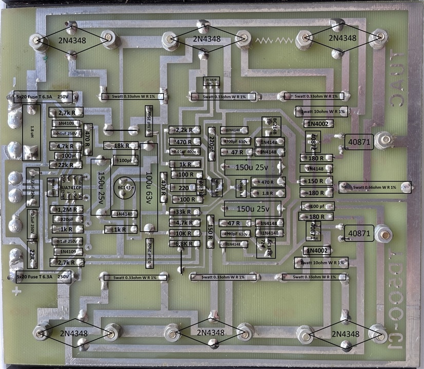
The simple markings on photo does not have the Anode and Cathode marked.
Please reload the page as I have updated the last image.

Thanks for the pics, they helps a lot I'm doing some measurements, soldering and waiting for several new components..
It is very hard to find 630v for the 4700pF, but I should be able to use 250v for the 4700pF and 0.01uF as you have. I assume they are replaced earlier on mine.
There is no need for a 630V cap in that position. The max voltage difference on the amplifier board is about 120V so even a 250V cap gives you massive margin.
MK
At least you can see the polarity of the diodes and the zeners are BZY series. The wirewound resistor at the end has been massively upgraded with two in series
You can also change all the power transistors to MJ15003 as they are easy to get