


Table of Contents
Introduction
There was a recent discussion regarding thoughts on a circuit for charging NiMH batteries. It was an interesting question, and I decided to see what was possible, initially just as a theoretical design. However, by accident, I now have a NiMH battery charging requirement of my own, so I decided to build the circuit, for a fully functioning charger project.

It might seem anachronistic to want to use NiMH batteries, however the technology is very mature, generally safe and low-cost. It's easy for a consumer to buy various NiMH batteries. As well as the usual cylindrical single cells, there are NiMH battery packs intended for cordless phones, and PCB-fitted NiMH coin cells for battery backup purposes.
This blog post documents a design that should work with a variety of NiMH batteries (single or multiple cells) by tweaking a resistor value to adjust the charge current. A PP3 battery connector is fitted, but it could be replaced with two leads and a suitable plug or other connection for the desired NiMH cell or battery pack. Another way to use this project is to integrate the board into the enclosure for projects that need battery power, i.e. to retrofit charging capability into an existing project.
The charging circuit does not rely on specific NiMH charging integrated circuits, which can become obsolete or are sometimes intended for a certain number of cells in the battery pack. Nearly all parts used are jellybean.
However, it should be noted that the circuit proposed is not very energy-efficient; it relies on linear power circuitry and, therefore, will dissipate heat while charging. On the plus side, the circuit should be (hopefully!) reliable in part due to its simplicity (probably the reason why so many commercial NiMH chargers traditionally were based on linear circuitry too), and there's no risk of software errors because there is no software.
This project is standalone without a microcontroller, but there is an optional interface to attach an Arduino or alternative controller board if desired.
It is really easy to use; select the desired charge current using the rotary control (this changes a resistance value to one of several settings), insert the battery, and leave it to charge. The orange LED turns on while charging, and the green LED indicates when the charge is complete and stopped.
There’s a third LED (red) which shouldn’t turn on in normal use; it indicates over-temperature and the charging is paused until the temperature drops.
Charging Principle and Features
NiMH (also written as Ni-MH) cells and batteries are usually charged at a constant current. The charge termination decision is a little complex, however. One well-known technique is to monitor the battery voltage, and when it dips briefly over a short period of time, that’s the indication that the battery is charged. The amount of voltage dip is small (often just a few tens of mV), so for further reliability, additional techniques are OR’d into the termination decision-making algorithm.
There’s another charging method, too. According to my interpretation of some battery manufacturer documents, it is safe to charge a Ni-MH battery at a rate of 0.1C for at least 24 hours, if not for weeks or months, or even a year. The battery ought to be fully charged within about 16 hours at that 0.1C rate. I decided to go with this method rather than utilize fast charging. It eliminates the need to have to identify the voltage dip. NOTE: Please consult the battery documentation and do not rely on the 0.1C assumption, just in case your battery requires a different charge rate!
For safety reasons, it would be good to cut off the charging if the battery warms up; the circuit contains a thermistor for that purpose.
The circuit implements a timer as well, in case the user forgets to unplug the charger after a day.
Circuit Description
The entire electronics of the project are described here, split up over three circuit diagrams describing (a) the main circuitry, (b) 5V power supply, and (c) timer.
Here is the first part:

From left to right, this circuitry consists of a temperature threshold monitor, which activates when the voltage across the 10 kohm thermistor drops below 2.5 V (this will occur when the resistance drops to about 5.5 kohm). If that occurs, then Q1 switches off. In normal use, it’s unlikely that the battery will warm up, so the temperature cut-out should not happen, but it can be tested by warming up the thermistor by hand. It is situated on the PCB very close to the battery positive terminal. If you’re using a different battery connector, then you may want to install the thermistor on wires, glued against the battery holder for instance.
The center portion of the circuit controls power to the charger using MOSFET Q2 and NPN transistors Q3 and Q6. In normal use Q3 is always turned on. When the timer expires, it is forced off using Q6.
The right side of the schematic contains the actual charging circuitry. U2 and Q4 provide a constant current governed by the chosen resistor selected through the rotary switch. The circuit works by maintaining a fixed known voltage (2.5V) across a resistance. I’ve used resistance values for 20 mA to 30 mA, corresponding to batteries with a capacity of 200 mAH to 300 mAH. You could change the resistor values to support different NiMH batteries. It may involve uprating some components.
Some of the connections in the circuit diagram above are brought out to connectors J3 and J4, which may be useful for attaching to a microcontroller in future. The board contains a 5V supply, a spare LED, and a push-button for a microcontroller-based user interface. This is shown in the circuit here:

The 19-hour timer uses several 74HC4060 divider ICs, all chained together to convert the 8 MHz clock into a signal that will go high after 19 hours (plus 5 minutes and 19 seconds, to be precise!). When it does, the count is prevented from increasing further, using U7 to force the RS pin (a clock pin) of U5 high until the board is power-cycled. U8 is a reset IC that automatically resets all the 74HC4060 chips upon power-up.
If you need a different timeout value, the simplest way may be to swap out the crystal for a different value. Otherwise, you could perhaps cut a trace and use a different divider output.

A Worked Example: 4 x AA Cells
The formula for the resistor between Q4 Emitter and Ground is R (in ohms) = 2500 / I, where I is the desired charging current in milliamps.
Note that if you plan to use a higher charging current (e.g., for AA-sized cells or packs of AA cells), then you’ll need to do the sums to determine if the resistor or if Q4 will overheat. You could add a heatsink to Q4 and/or reduce the supply voltage from 24V to (say) 12V.
You may also need to reduce the value of R9, as discussed further below.
Note that the constant current circuit is linear, so heat will be dissipated from the transistor Q4, as well as the resistor from Q4’s emitter to the ground.
For example, let’s say you wish to charge a battery pack of four 2800 mAH cells; these could be high-capacity AA cells. The charging current (at 0.1C) would be 280 mA, and therefore, the resistor would be 8.9 ohms, and the power dissipated in it would be I2R, i.e., 0.28*0.28*8.9 = 0.7W. A 1W resistor could be chosen.
For such an example, the power dissipation in the diode D2 would be in the region of 280 mW, so a 0.5W diode would be selected.
With a worst-case excessively discharged battery pack, let’s say the voltage is 0.5V per cell, and therefore, the 4xAA battery pack voltage would be 2V. If we choose a supply voltage of 12V, then Q4 will see about 12-0.7-2.5-2V (where 0.7V is the diode voltage drop, and 2.5V is a constant for the TL431 reference) across the collector-emitter terminals, i.e. 6.8V, so the power dissipation would be 6.8*0.28 = 1.9W. You’d need a metal enclosure or a heatsink, and screw the transistor to it.
The base of Q4 needs to be at about 3.2V, and about 280 / 100 mA, i.e., 2.8mA may flow through the base connection, and allowing an additional 1mA for the voltage reference, this means the resistor R9 must have a value lower than (12-3.2)/(2.8+1) kohms, which is about 2.3 kohm. I’d probably choose a resistance of 1 kohm since the current gain of the transistor isn’t always a well-defined single value.
If you want to build such an example as the one described in this section, then see the Type 2 circuit board below.
Building It
This project has two options. Circuit board Type 1 is the one that was actually constructed, and it has space for a PP3 battery holder.
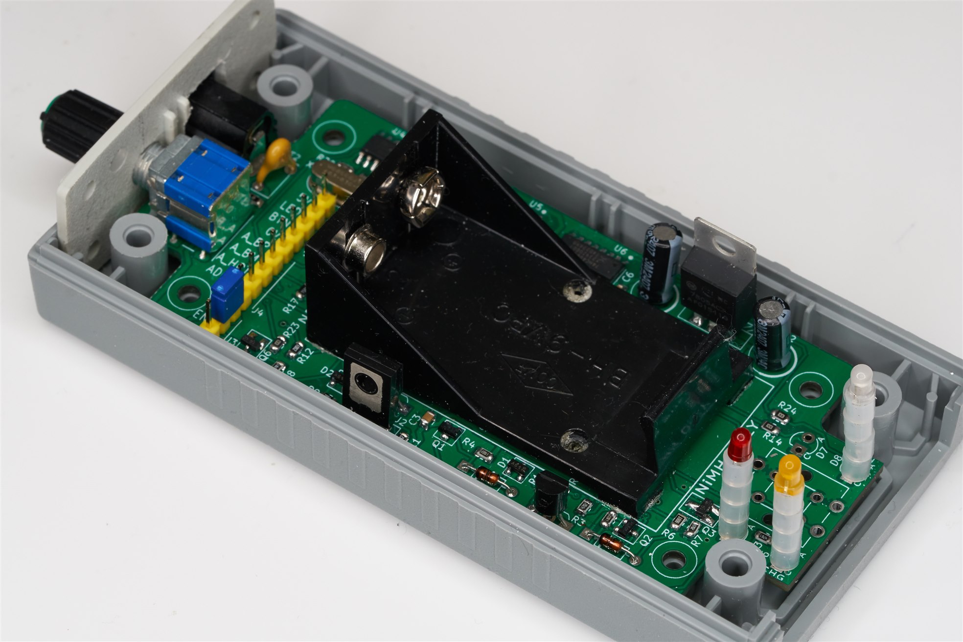
Circuit construction is straightforward; there’s nothing special to discuss. The PCB Gerber files were sent to a PCB manufacturer, and when it returned, I populated it using the bill-of-materials.
The photo below shows the cut-outs needed for the barrel DC socket and the charge current selection knob.

Board Type 2 (Gerber files) omits the battery holder, and upsizes some of the components, to make it suitable for higher capacity NiMH batteries.
The Type 1 schematic was shown earlier. The Type 2 board difference is shown below.

Here is what the Type 2 board looks like (this is a render; I have not constructed it, so I am not sure, but hopefully, there are no major errors!).

Tests
Confirming the operation of the sub-modules is straightforward. Connect the power supply to the charger (with no battery connected). The yellow LED should light to indicate that the charging circuit is enabled.
Heating the thermistor slightly with a hot-air tool should cause the red over-temperature LED to switch on, and the yellow charging LED should switch off.
Next, after the temperature of the thermistor has cooled down, set your multimeter to milliamps DC and place it across the battery charging terminals (with no battery attached). You should measure a current between 20 and 30 mA, depending on the rotary switch setting. Note that if you’ve modified the circuit to support a much larger capacity battery, then it’s not good to measure the current in this way for an extended amount of time because the transistor Q4 will get hot – it’s a linear charger, so the heat needs to dissipate somewhere!
One more test; leave the charger powered up for 19 hours. At the end of that period (19 hours, 5 minutes and 19 seconds), the yellow LED should extinguish, and the green LED will be lit.
Summary
It is possible to charge a NiMH battery at a 0.1C rate for about 16 hours. A circuit was developed to do just that, and it includes over-temperature charge cut-out, and a 19-hour timer.
It was tested with a PP3 8.4V NiMH battery. The circuit is also suitable for other NiMH batteries, with some component changes.
See the GitHub page for downloads including schematic, Gerber files and bill-of-materials if you’re interested in assembling this project.
Thanks for reading!

