element14 Community
element14 Community
    Register Log In
  • Site
  • Search
  • Log In Register
  • Community Hub
    Community Hub
    • What's New on element14
    • Feedback and Support
    • Benefits of Membership
    • Personal Blogs
    • Members Area
    • Achievement Levels
  • Learn
    Learn
    • Ask an Expert
    • eBooks
    • element14 presents
    • Learning Center
    • Tech Spotlight
    • STEM Academy
    • Webinars, Training and Events
    • Learning Groups
  • Technologies
    Technologies
    • 3D Printing
    • FPGA
    • Industrial Automation
    • Internet of Things
    • Power & Energy
    • Sensors
    • Technology Groups
  • Challenges & Projects
    Challenges & Projects
    • Design Challenges
    • element14 presents Projects
    • Project14
    • Arduino Projects
    • Raspberry Pi Projects
    • Project Groups
  • Products
    Products
    • Arduino
    • Avnet Boards Community
    • Dev Tools
    • Manufacturers
    • Multicomp Pro
    • Product Groups
    • Raspberry Pi
    • RoadTests & Reviews
  • Store
    Store
    • Visit Your Store
    • Choose another store...
      • Europe
      •  Austria (German)
      •  Belgium (Dutch, French)
      •  Bulgaria (Bulgarian)
      •  Czech Republic (Czech)
      •  Denmark (Danish)
      •  Estonia (Estonian)
      •  Finland (Finnish)
      •  France (French)
      •  Germany (German)
      •  Hungary (Hungarian)
      •  Ireland
      •  Israel
      •  Italy (Italian)
      •  Latvia (Latvian)
      •  
      •  Lithuania (Lithuanian)
      •  Netherlands (Dutch)
      •  Norway (Norwegian)
      •  Poland (Polish)
      •  Portugal (Portuguese)
      •  Romania (Romanian)
      •  Russia (Russian)
      •  Slovakia (Slovak)
      •  Slovenia (Slovenian)
      •  Spain (Spanish)
      •  Sweden (Swedish)
      •  Switzerland(German, French)
      •  Turkey (Turkish)
      •  United Kingdom
      • Asia Pacific
      •  Australia
      •  China
      •  Hong Kong
      •  India
      •  Korea (Korean)
      •  Malaysia
      •  New Zealand
      •  Philippines
      •  Singapore
      •  Taiwan
      •  Thailand (Thai)
      • Americas
      •  Brazil (Portuguese)
      •  Canada
      •  Mexico (Spanish)
      •  United States
      Can't find the country/region you're looking for? Visit our export site or find a local distributor.
  • Translate
  • Profile
  • Settings
Power & Energy
  • Technologies
  • More
Power & Energy
Blog Building a Smart Electronic Load | Introduction (#1)
  • Blog
  • Forum
  • Quiz
  • Documents
  • Polls
  • Events
  • Mentions
  • Sub-Groups
  • Tags
  • More
  • Cancel
  • New
  • Share
  • More
  • Cancel
Group Actions
  • Group RSS
  • More
  • Cancel
EMI-Reduction-Techniques
Engagement
  • Author Author: Attila Tőkés
  • Date Created: 30 Dec 2024 6:56 PM Date Created
  • Views 919 views
  • Likes 14 likes
  • Comments 5 comments
  • esp32
  • electronic load
Related
Recommended

Building a Smart Electronic Load | Introduction (#1)

Attila Tőkés
Attila Tőkés
30 Dec 2024

It happens that I had a couple of LGA775 coolers laying around from an old PC. The PC these cooler belonged to was discarded a long time ago, but I kept the coolers to be used in future power electronic projects. Back in November I decided to try to build some electronic loads from them.

This blog post show the first, somewhat working, prototypes of the electronic loads:

image

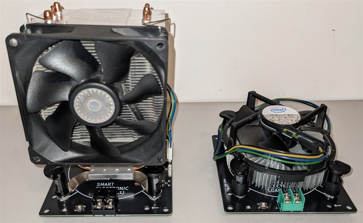
You may have noticed that user "interface" of the loads is literally one push button and one LED. That's because the loads are supposed to be "smart" electronic loads, not just simply programmable dummy loads. There are plenty of those on Ebay / AliExpress, so I could have just buy one.

The "smart electronic load" here means digital control (via an MCU) and connectivity (WiFi / BLE / USB). These should allow us implement some interesting features like dynamic load simulation and others.

In terms ideas / features (more like my wish list Innocent) I proposed this ones:

  • up to 100-300W load capacity - or whatever we can sweeze out from a LGA775 cooler
      
  • up to 100-200V load voltage
      
  • up to 30-50A continuous and >100A pulsed current
      
  • reasonable bandwidth (somewhere up to 100 kHz - 1 MHz) - to able to simulate short / high amplitude current pulses
      
  • WiFi and / or USB connectivity
      
  • reasonable price and no too special components that may become unavailable after some time
      

So, after some thinking and browsing other electronic load designs I came out with this schematics:

image

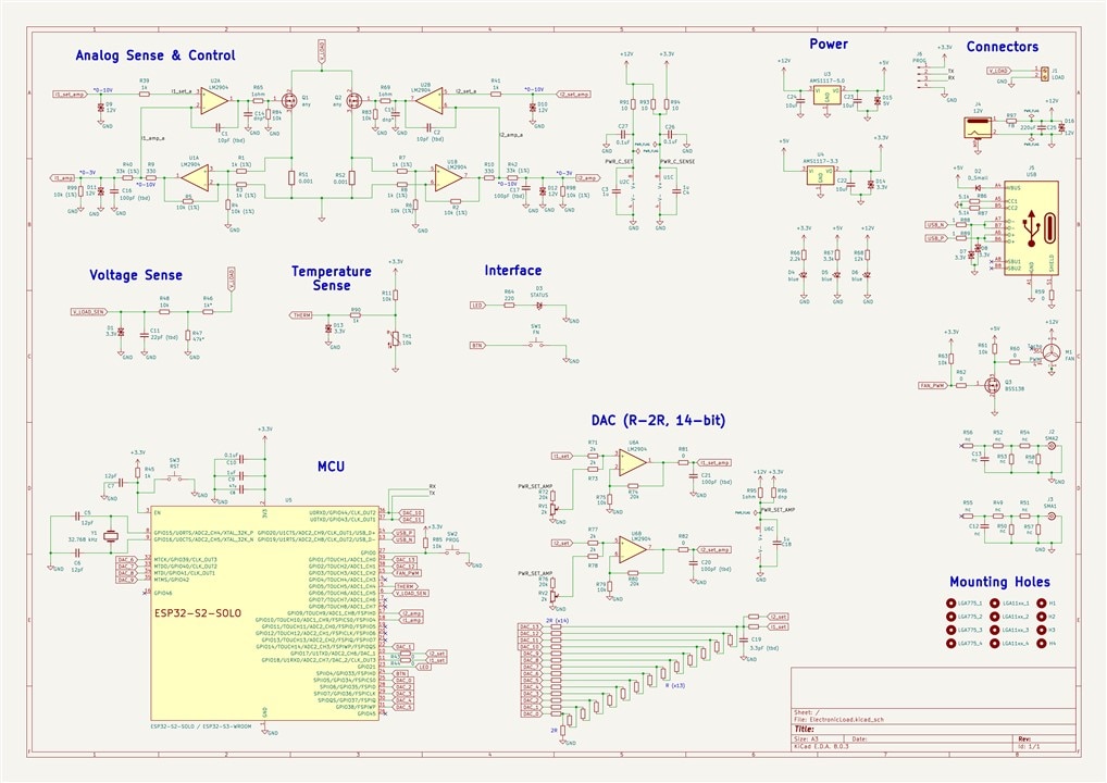
The design uses two MOSFET-s acting as variable resistors for the loads, with current sense resistors measuring the current flowing through the MOSFET-s. The current sense amplification and load control is implemented using dual op-amps. Other than that there is a MCU, a DAC, voltage and temperature sensing circuitry, PWM fan control and some miscellaneous stuff.

For the MOSFET-s in theory almost anything in a TO-247 or TO-220 package should work. For the dual op-amps I used standard 8-pin footprint, with many op-amps from various manufactures. In theory the load's performance should scale up with the performance of MOSTFET-s (load capacity) and op-amps (bandwidth).

For the MCU I went with the ESP32-S2-SOLO / ESP32-S3-WROOM modules (they have the same footprint), as it has the WiFi, USB and ADC-s. The ESP32-S2 is only included as an option as it has to DAC channels, otherwise the ESP32-S3 should be a better option.

As I suspected the ESP32-S2 DAC is kind of garbage (is seems to have an offset voltage of ~60-80mV), I also included a manually implemented 2R-R DAC (what could possibly go wrong Sweat smile). I went with this options as I did not find any cheap DAC with a reasonable bandwidth (ex > 200kHz), I needed an op-amp for voltage conversion anyway, and a 2R-R looked to be relatively simple to implement.

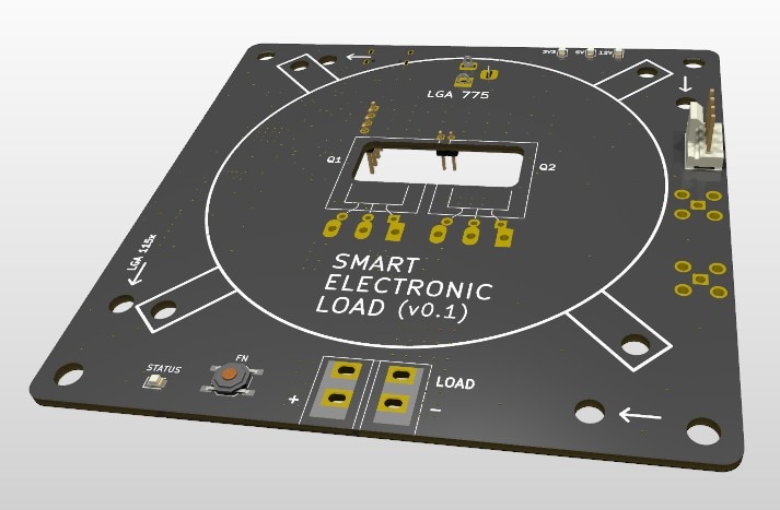
The PCB is a 10x10 cm (so it can be cheaply manufactured) and it is designed around the LGA775 cooler footprint.

imageimage

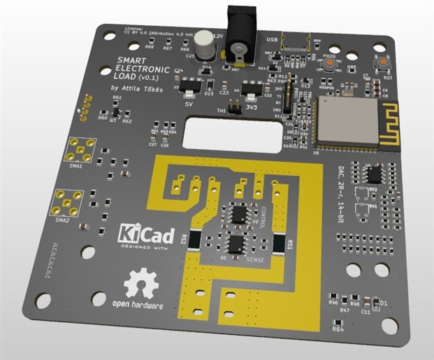
This is what the assembled to prototype looks like:

image
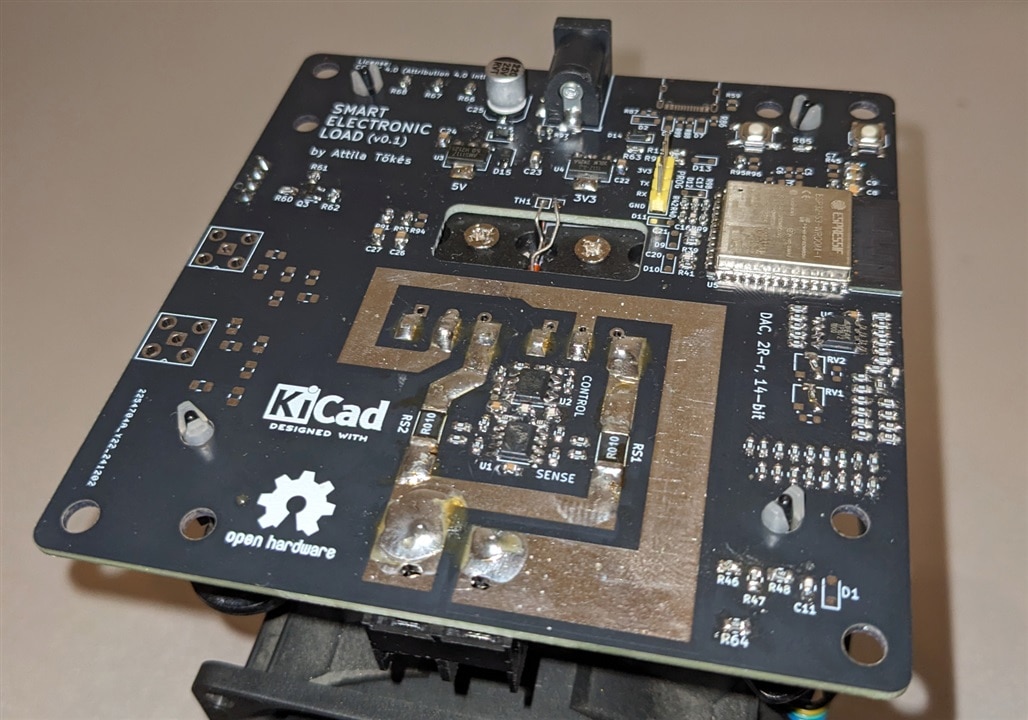
(sorry for the dirty board and shitty soldering Smiley)

Surprisingly, the load already seems to be somewhat (!) working:

image

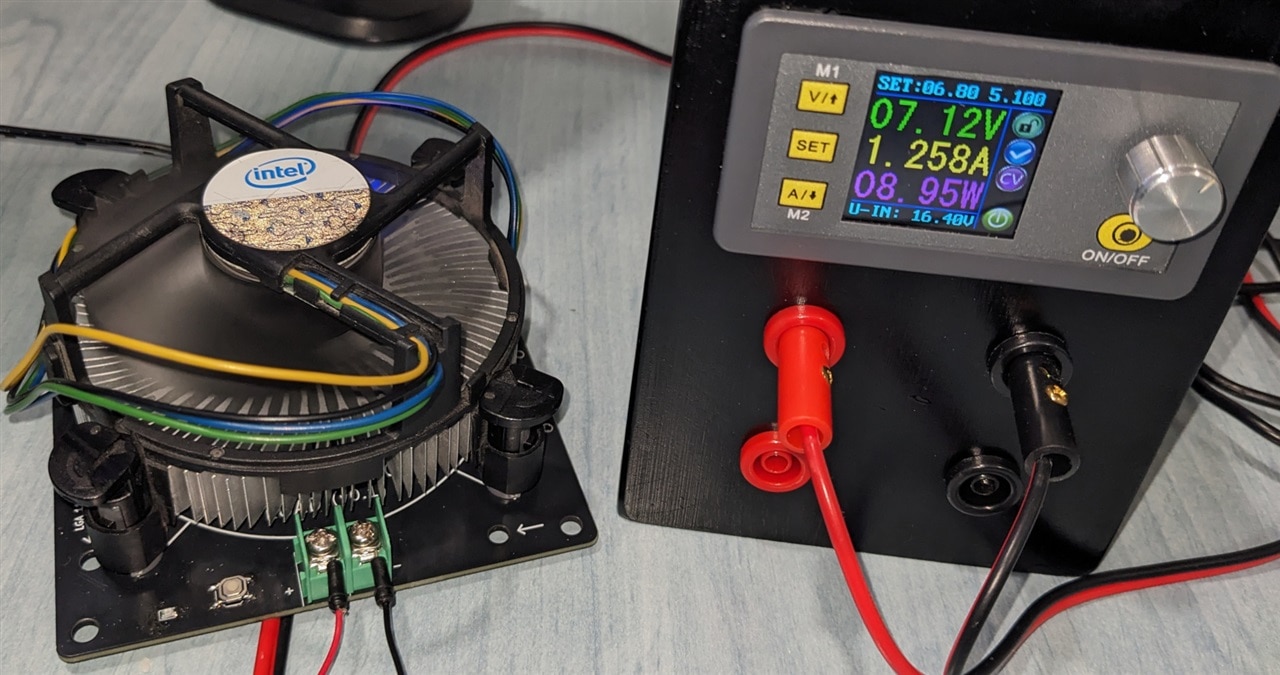
...by that I mean it is able to sink a programmed current, but is not very linear, and looking with the scope there are some oscillations. I think the op-amp stage in the DAC may be picking up some noise, and this causes the load control stage to drive the MOSFETS all over the place.

Other than this, the input voltage sense stage seems to work (initially it had a wrongly implemented voltage divider so I almost fried the ESP32). The temperature sensing, FAN control, USB and others were not yet tested.

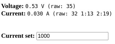
The firmware is basically nonexistent. I just threw a couple of lines of Arduino code on the ESP32 for testing. The interface will be Web based, but current I only have this:

image

So, what do you think about the project? Sunglasses Also, if you want to contribute, or just build an electronic load for yourself, let me know.

Github repo (with KiCAD and FreeCAD drawing files):

https://github.com/bluetiger9/SmartElectronicLoad

  • Sign in to reply

Top Comments

  • michaelkellett
    michaelkellett 6 months ago +2
    Try simulating your analogue stages. There are several things that don't look good. Your spec is incredibly ambitious - much faster than commercial ELs costing many £k. The LM2904 has an open loop…
  • dougw
    dougw 6 months ago +1
    Interesting build. An electronic load is on my list of things to build or acquire.
  • Attila Tőkés
    Attila Tőkés 6 months ago in reply to michaelkellett +1
    michaelkellett , t hanks for the feedback! It's very useful. Hmm, the LM2904 is just a leftover label. I used it as it was already in the KiCad library, but it is supposed to be a generic 8-pin dual…
  • DAB
    DAB 6 months ago

    A very interesting project.

    I like projects that try to reuse materials.

    This one will keep you busy for a while trying to resolve the issues.

    • Cancel
    • Vote Up 0 Vote Down
    • Sign in to reply
    • More
    • Cancel
  • michaelkellett
    michaelkellett 6 months ago in reply to Attila Tőkés

    On a job like this I would recommend the use of op amps from TI or Analog Devices because the quality of the simulation models from those two companies is generally very good. I've used 3Peak op amps in production designs but the tech support is far inferior (although the parts seem OK and are cheap).

    You may well be able to tune out your HF oscillation by trying the suggestions I made earlier, and I agree that the 10Hz channel has some kind of problem (ie the ciruit on the board isn't what you intend.

    I've thought a lot about the MOSFET open drain to operation switch issue and the best idea I have so far is that it is necessary to monitor the source current and limit the gate voltage (by introducing an offset at the input of U2A) so that U2A does not try to overdrive the MOSFET. This will be difficult because the offset required is not linearly related to the current demand so would best be derived from a map in software. But this would then put a processor, ADC and DAC in the feedback loop around the MOSFET - so you end up with a DSP controlled load rather than nice simple analogue one. (HP did NOT do this !)

    Another possibility is to look (if possible) at how the experts have done it - schematics for modern electronic loads are not easily obtainable but there is a good service manual with full parts list and good quality schematics for the HP6060/63B here:

    https://www.keysight.com/us/en/assets/9018-40092/service-manuals/9018-40092.pdf

    It's well worth spending some time to see how they do it !

    I just splashed out some money on an HP load - I'll test it for the same issue.

    MK

    • Cancel
    • Vote Up +1 Vote Down
    • Sign in to reply
    • More
    • Cancel
  • Attila Tőkés
    Attila Tőkés 6 months ago in reply to michaelkellett
     michaelkellett , thanks for the feedback! Slight smile  It's very useful.

    Hmm, the LM2904 is just a leftover label. Grimacing  I used it as it was already in the KiCad library, but it is supposed to be a generic 8-pin dual-opamp there.

    The actual op-amp I'm currently using is a 3PEATP1672-SR. It has a 7MHz gain bandwidth product, 250uV max input offset 20V/μs slew rate and 70mA short circuit current. It is currently used for both the current sense, load control and DAC, but for those crazier specs I thought to use more performant op-amps with lower offset voltage (for the current sense) and higher output current (for the load control).

    For the MOSFET-s I choose a couple of not too expensive TO-247 and TO-220 packaged ones with decent looking specifications from LCSC. I mainly looked at higher current options (20-50A continuous) with decent thermal characteristics (power dissipation and thermal resistance). The MOSFET-s there are currently in the two loads are 2 x OSEN IRFP460PBF (supposedly 20A @ 500V, 80A pulsed) and 2 x FDP036N10A(UMW). I also ordered some other MOSFET-s, but for those self-destruction reason Robot, I mounted the cheapest ones first. :D

    For the current sense I'm currently using 0.1 ohm, and 0.01 ohms, with 10x amplification. The 0.001 ohm option was just for the higher current versions. The PCB layout is currently this:
    image
    In theory current should not flow in the sense paths...

    Regarding those specs, they are more like wishes for further iterations of the project, but based on specs of the MOSFET-s, op-amps and the ESP32, they may be achievable. Stuck out tongue winking eye 

    I also observed that 12V gate voltage phenomena when no input connected. The initial idea was to implement protections in software (by soft disabling the load / setting current to 0.0.A). Currently this does not really works, as because of various offset voltages a couple of mV could still get to the load control op-amp, and this causes the MOSFET gates to be set at 12V until there is some actual current draw.
    As now both loads are somewhat working, the plan is to take the project step-by-step from here. Sunglasses I want to build a basic firmware, then test each stage (current sense, load control, dac) separately, with proper oscilloscope probing.
      
    Without proper probing, I found a bit hard to investigate problems. For example the gates of one of the MOSTFET-s is driven like this:
    image
    but with being able to probe just one channel is pretty hard to find the cause of this. 
    So, I just disconnected this channel, and he other channel looks to fine. Minus some high frequency oscillations (674KHz instead of the 10 Hz above) at higher loads (this is at 35W):
    image
    Thanks,
    Attila
    • Cancel
    • Vote Up +1 Vote Down
    • Sign in to reply
    • More
    • Cancel
  • michaelkellett
    michaelkellett 6 months ago

    Try simulating your analogue stages.

    There are several things that don't look good.

    Your spec is incredibly ambitious  - much faster than commercial ELs costing many £k.

    The LM2904 has an open loop bandwidth of 0.7MHz and a slew rate of only 0.5V/us. The typical offset is 0.3mV (max 3mV) , equivalent to 0.3A (max 3A) output current offset error.

    The 2904 won't take kindly to driving a big MOSFET gate with a 1R series resistor  - increase it to at least 47R - but note that it is usually necessary to tune the series R according to the MOSFET gate capacitance and the feedback loop compensation.

    Increase R9 to at least 1k and expect C1 to be of the order of 4.7nF. (30kHz bandwidth)

    Never fit C14.

    You have a differential amplifier in the feedback loop of U2A and this can be difficult to compensate - simulation will help.

    Think about using a better op amp than the LM2904 (lower offsets, faster slew rate, greater bandwidth - OPA192 would suit).

    Maybe increase the value of the current sense resistor to 0.01R - it will fry at 100A and dissipate 9W at 30A, other problems will be reduced.

    Managing good Kelvin connections to a current sense resistor on a PCB requires great skill at 0.001R or an expensive 4 terminal sense resistor.

    No (common)  MOSFET can cope with 100A @ 200V - but with your circuit as it stands if you set it for 0.1A and connect it to a 200V source it will attempt to do that. (Not 0.1A but > 100A). This is because when the drain ciruit of the MOSFET is open and there is any current demand all then the feedback loop will increase the voltage on the MOSFET gate to about 12V. The LM2904 is slow and once current starts to flow it will take about 20us to switch the MOSFET off.

    Many commercial loads (and almost all DIY designs) suffer to some extent from this problem. Most commercial loads won't actually self destruct if connected to a stiff high voltage source.

    If you want fast pulses then protection gets very difficult. My usual approach is a M0SFET switch and a power resistor - and beware - even that can oscillate under some circumstances.

    Hope some of this helps.

    MK

    • Cancel
    • Vote Up +2 Vote Down
    • Sign in to reply
    • More
    • Cancel
  • dougw
    dougw 6 months ago

    Interesting build. An electronic load is on my list of things to build or acquire.

    • Cancel
    • Vote Up +1 Vote Down
    • Sign in to reply
    • More
    • Cancel
element14 Community

element14 is the first online community specifically for engineers. Connect with your peers and get expert answers to your questions.

  • Members
  • Learn
  • Technologies
  • Challenges & Projects
  • Products
  • Store
  • About Us
  • Feedback & Support
  • FAQs
  • Terms of Use
  • Privacy Policy
  • Legal and Copyright Notices
  • Sitemap
  • Cookies

An Avnet Company © 2025 Premier Farnell Limited. All Rights Reserved.

Premier Farnell Ltd, registered in England and Wales (no 00876412), registered office: Farnell House, Forge Lane, Leeds LS12 2NE.

ICP 备案号 10220084.

Follow element14

  • X
  • Facebook
  • linkedin
  • YouTube