


When I saw Michael's that's being designed here in the community, I remembered I have a switch mode transformator in my scrap parts box.
It's there since forever. I unsoldered it when throwing away a consumer product. Not to be reused in a circuit, but as a source for enamelled wire.
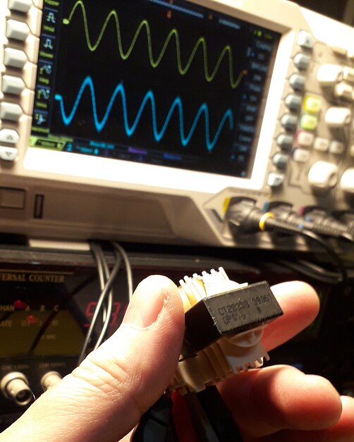
The transfo has 12 pins. It's been so many years ago that I couldn't remember where I got it from.
Out of curiousity I'm trying to find out what the layout of the windings is and how it was used.
The mistery is resolved; Google tells it's from an old Philips VCR video recorder. And I found the schematics and operating principles back.
I did the first investigations yesterday before I had found the info back. Turns out I was on the right path.
Find the coils
I first measured the resistance between pins. That shows which ones have a coil between them.
Because that's a DC measurement, it does not reveal the polarity (where winding #1 is). But it gets a first layout on paper:
| resistance measurement | coils layout |
|---|---|
 |
ignore the 2 text annotations, that was added later when I found info on internet |

The transfo has 2 primary windings, 2 single secondary ones, and a 3rd secondary with 2 taps in between.
Find Polarity and Windings Ratio
I then switched to AC to find direction of each coil relative to the 1st primary one, and the ratio.
I put a 400 mV RMS sinus on the first winding; at 400 kHz. Then checked the other windings with an oscilloscope.
If the other winding is in phase, the direction is identical, else it has an opposite winding direction.
pin 5 - 6: 2nd primary winding:
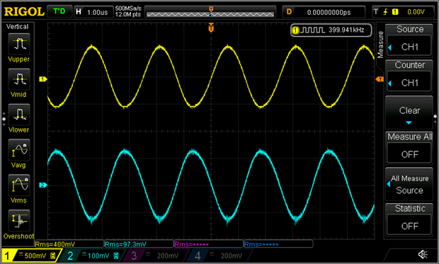
You can see that the phase is opposite. This coil is wound in the opposite direction of the 1st primary.
ratio is 100 mV / 400 mV = 4:1
10-11: 1st secondary winding:
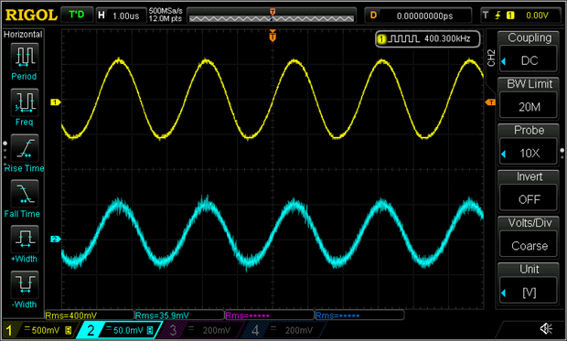
The 3 secondary windings all have the same direction.
The ratio for this one is 36 mV / 400 mV = 11:1
12 - 13: 2nd secondary:
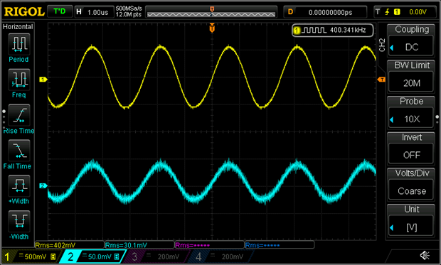
30 mV / 400 mV = 13:1
14 - 15 -16 - 17: the 3 windings in series
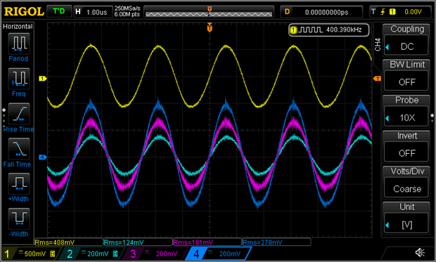
Here, the first part is:
124 mV / 400 mV = 3:1
middle part:
(181 mV - 124 mV) / 400 mV = 6:1
right part:
(278 mV - 181 mV) / 400 mV = 4:1
Datasheets and Service Manuals
Since then I found good information on the internet. It wasn't an easy find because I couldn't locate a spec for the transformator, and the serial number is used for at least 4 different coil configurations.
Turns out that the exact configuration was used in a Philips VR 120 VCR. And that sounds right. I've taken parts out of several video recorders in the day (motors, opto-couplers and transformators.
Here is the transformer layout from the service manual:. As you can see, very close to my findings.
They show one more winding between pin 17 and 18 that's not used. On my transformator, that winding and the pin aren't available.
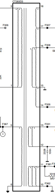
source: https://elektrotanya.com/ Philips Apollo 13 service manual
The Schematics
The design is built around a n MC44608. Switching frequency is 40 kHz (oops, I did the ratios an order of magnitude too high)
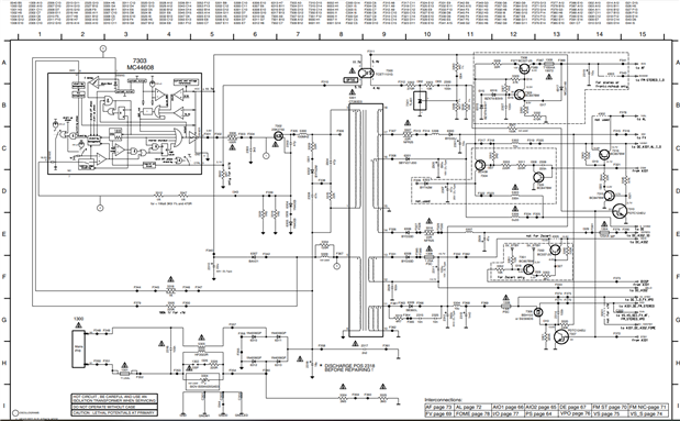
source: https://elektrotanya.com/ Philips Apollo 13 service manual
The supply is intended to work low power in stand-by mode. You can see that there are STBY switch transistors in the secondary circuits.
Some of the rails have a branch for stand-by and on, each catering for the relevant circuits in the recorder (notably the remote control detector and the µcontroller (Toshiba TMP93CT76) that needs to be awake to perform pre-programmed recordings.
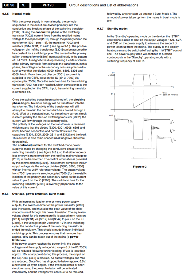
Principles:
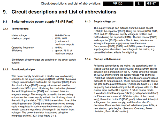
source: https://elektrotanya.com/ Philips Apollo 13 service manual
source: https://elektrotanya.com/ Philips Apollo 13 service manual
Top Comments
-

Jan Cumps
-
Cancel
-
Vote Up
0
Vote Down
-
-
Sign in to reply
-
More
-
Cancel
Comment-

Jan Cumps
-
Cancel
-
Vote Up
0
Vote Down
-
-
Sign in to reply
-
More
-
Cancel
Children