element14 Community
element14 Community
    Register Log In
  • Site
  • Search
  • Log In Register
  • About Us
  • Community Hub
    Community Hub
    • What's New on element14
    • Feedback and Support
    • Benefits of Membership
    • Personal Blogs
    • Members Area
    • Achievement Levels
  • Learn
    Learn
    • Ask an Expert
    • eBooks
    • element14 presents
    • Learning Center
    • Tech Spotlight
    • STEM Academy
    • Webinars, Training and Events
    • Learning Groups
  • Technologies
    Technologies
    • 3D Printing
    • FPGA
    • Industrial Automation
    • Internet of Things
    • Power & Energy
    • Sensors
    • Technology Groups
  • Challenges & Projects
    Challenges & Projects
    • Design Challenges
    • element14 presents Projects
    • Project14
    • Arduino Projects
    • Raspberry Pi Projects
    • Project Groups
  • Products
    Products
    • Arduino
    • Avnet Boards Community
    • Dev Tools
    • Manufacturers
    • Multicomp Pro
    • Product Groups
    • Raspberry Pi
    • RoadTests & Reviews
  • Store
    Store
    • Visit Your Store
    • Choose another store...
      • Europe
      •  Austria (German)
      •  Belgium (Dutch, French)
      •  Bulgaria (Bulgarian)
      •  Czech Republic (Czech)
      •  Denmark (Danish)
      •  Estonia (Estonian)
      •  Finland (Finnish)
      •  France (French)
      •  Germany (German)
      •  Hungary (Hungarian)
      •  Ireland
      •  Israel
      •  Italy (Italian)
      •  Latvia (Latvian)
      •  
      •  Lithuania (Lithuanian)
      •  Netherlands (Dutch)
      •  Norway (Norwegian)
      •  Poland (Polish)
      •  Portugal (Portuguese)
      •  Romania (Romanian)
      •  Russia (Russian)
      •  Slovakia (Slovak)
      •  Slovenia (Slovenian)
      •  Spain (Spanish)
      •  Sweden (Swedish)
      •  Switzerland(German, French)
      •  Turkey (Turkish)
      •  United Kingdom
      • Asia Pacific
      •  Australia
      •  China
      •  Hong Kong
      •  India
      •  Korea (Korean)
      •  Malaysia
      •  New Zealand
      •  Philippines
      •  Singapore
      •  Taiwan
      •  Thailand (Thai)
      • Americas
      •  Brazil (Portuguese)
      •  Canada
      •  Mexico (Spanish)
      •  United States
      Can't find the country/region you're looking for? Visit our export site or find a local distributor.
  • Translate
  • Profile
  • Settings
Power & Energy
  • Technologies
  • More
Power & Energy
Blog Early-Access Review (Pt 2): Epishine Light Energy Harvesting Module Evaluation Kit
  • Blog
  • Forum
  • Quiz
  • Documents
  • Polls
  • Events
  • Mentions
  • Sub-Groups
  • Tags
  • More
  • Cancel
  • New
  • Share
  • More
  • Cancel
Group Actions
  • Group RSS
  • More
  • Cancel
EMI-Reduction-Techniques
Engagement
  • Author Author: Gough Lui
  • Date Created: 5 Aug 2020 8:45 AM Date Created
  • Views 2266 views
  • Likes 6 likes
  • Comments 5 comments
  • photovoltaics
  • test
  • organic photovoltaics
  • ambient energy
  • energy harvesting
  • organic solar cells
  • evaluation kit
  • epishine
  • energy harvester
  • battery
  • review
  • ambient light
  • low-power
  • iot
  • energy
  • solar energy
  • photovoltaic
Related
Recommended

Early-Access Review (Pt 2): Epishine Light Energy Harvesting Module Evaluation Kit

Gough Lui
Gough Lui
5 Aug 2020

After putting out my initial review on the kit, I somehow felt the review to be a little incomplete, since the star of the show was the organic photovoltaic (OPV) panel and I didn’t really do much to test the panel on its own. The design of the kit doesn’t make it easy to test the panel independently of the harvesting circuit, but that doesn’t mean that it can’t be done.


After some head-scratching, I decided that if I was willing to give it a try even if it meant sacrificing the kit “in the name of science”. After all, that’s what evaluation kits are for, and besides, I think we’ve already learned a lot from it in the first part.


The OPV Module

Data on the OPV module was not provided, so this section will be dedicated to trying to characterise the performance of the OPV module and have a guess at its capabilities. Unfortunately, I don’t have access to a solar simulator, spectrometer, radiometer, reference cell or temperature-controlled environment, so everything will be done on the “cheap” based on what I have to hand. Don’t expect figures that are accurate to even a single decimal place.

image

Step one was to gain access to the module itself. Based on some quick tracing, it seems the kit has a common ground, so I isolated the positive tab by carefully heating up the tab with flux and desoldering braid and wicking away enough solder to allow the tab to come free. I took a few breaks in-between, while also using tweezers to grab the tab to try and provide a little heat-sinking so heat did not travel up to the crimp inside the panel. Once it had been freed, the tab was bent back and wires were attached to both positive and negative for measurements.

image

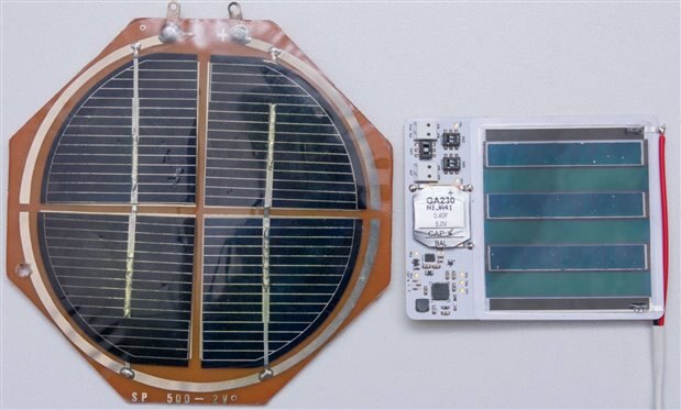
For the purpose of a reference cell, I used an old “hobby cell” that I purchased around 17 years ago from a local electronics shop. This one is rated 2V, 500mA but what this rating means in practice is a bit nebulous. I expect based on the area of the cell (7717mm2) and the ratings that it has approximately 13% energy conversion efficiency under standard AM1.5 conditions (1000W/m2) which fits well with the cells of the time (although perhaps 12% is closer to reality). By comparing the outputs of each cell on an area basis, it may be possible to determine the (approximate) efficiency of the OPV cell (which has an area of 2500mm2).

image

Tests were performed using an IKEA Tertial desk lamp situated above the test panel by a small fixed distance of 20mm. The panel was centred in the field of light and an I-V curve was taken using a Keithley 2450 SMU under SCPI remote control using pyvisa and a script I developed. The light sources were a 11W 1050lm Warm White LED light and a 60W frosted incandescent globe, both of which are expected to have very similar visual brightness but the incandescent would have a continuous black-body-like spectrum more akin to the sun.

image

Under the LED source, the reference panel developed 87.3mW of output which is approximate 11.3µW/mm2. The fill factor was a very average 0.669. Perhaps it developed a little less than expected power due to the distribution of light from the LED globe.

image

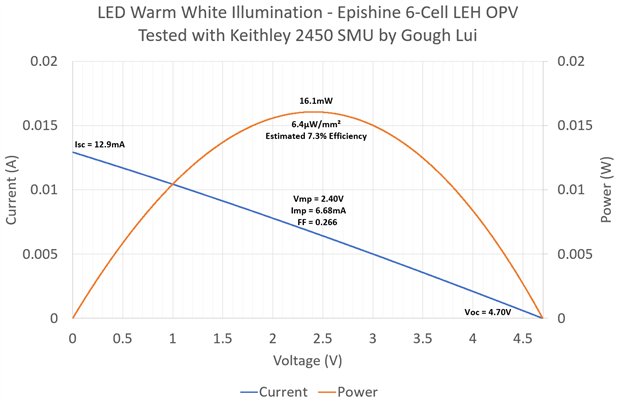
Swapping in the OPV panel into the same lighting condition, it developed 16.1mW with an I-V curve that looked like a straight line. This resulted in a poor fill factor of just 0.266, which suggests to me that the OPV technology may have a lot of recombination sites, short minority carrier lifetimes and high series resistances to worry about. The area-normalised power output was 6.4µW/mm2 which suggests the OPV panel achieved around 7.3% efficiency as a ballpark figure (possibly 6-8% more realistically). This is roughly the same ballpark figure for amorphous silicon on glass (i.e. “brown”) panels commonly used in low-cost consumer electronics which is not a bad thing, but its longevity remains to be determined.

image

Moving to the incandescent source, the reference cell produced much better results, now producing 407mW. Despite looking visually similar, the increased long-wavelength bias in the output spectra may have contributed to more power output although the panel was also heated quite substantially resulting in a significant loss of open circuit voltage and a reduction in fill factor to 0.459. The area normalised output was 52.7µW/mm2.

image

Under this condition, the OPV panel did not see any improvement – in fact, the produced power decreased slightly to 13.7mW and the area normalised power is now 5.48µW/mm2. The fill factor also remains relatively unchanged at 0.273, suggesting to me that the panel may have “saturated” even under the previous testing condition or is very adversely affected by the heat from the light. Whatever the reason, this result was not something I had expected.

imageimage

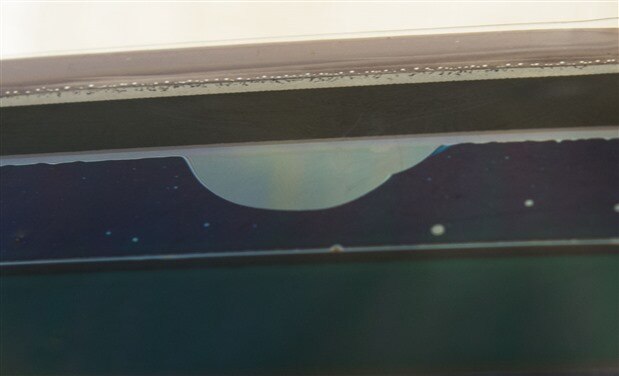
I was, perhaps, too ambitious in this test, as the heat did not leave the panel unscathed. It seems that a bubble has formed, a sign of delamination of the layers of the OPV panel. Despite the plastic appearing transparent, there may be a transparent coating of conductive material and the loss of contact area would increase the series resistance, reducing the panel’s efficiency. A closer look at the panel, even initially, showed some level of bubbles in the panel which suggests delamination could be possible if placed under stress. Once the bubble got somewhat large, poking at it only resulted in it growing. Because of this, I consider this OPV cell to be compromised.

image

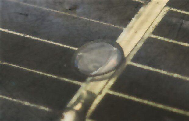
The reference cell too, managed to bubble, as it had a clear plastic encapsulation (partly yellowed) that had probably become partially “liquid” and a bubble formed. This is not too problematic in this case, as the cell is the monocrystalline wafer underneath the encapsulant, although the bubble could affect the absorbance of light in that small area.


Battery Backup

Now that the OPV panel had been disconnected from the circuit, it was probably a good opportunity to try and establish the conversion penalty of drawing down the primary battery backup to power a load. I planned to use the Keithley 2450 SMU to provide an accurate low-current load on the output of the kit and use the Rohde & Schwarz NGM202 to provide the input to the battery terminal, averaging the readings over time using its onboard statistics function to determine the efficiency.

image

Unfortunately, after piecing together the kit and flipping the jumper to the primary battery back-up position, I wasn’t able to get any output to be developed. I suspect the kit may not want to start-up from “cold” without any input from the PV, or perhaps there maybe something wrong with the kit. I measured the voltage on the rear of the battery input connector and it was correctly reading, the current drawn remained pretty much zero even with the supercapacitor voltage below the output voltage.


Conclusion

This second (and perhaps final) installment covers the Epishine Light Energy Harvesting module itself. By modifying the kit to gain access to the organic photovoltaic cell, it was possible to test it under controlled indoor “high intensity” warm-white LED and incandescent lighting scenarios. The panel, when compared to the monocrystalline reference under the warm-white LED scenario, demonstrated an output which implies an efficiency around 6-8%, similar to amorphous silicon on glass cells. Perhaps being too ambitious, I tested with an incandescent source which seemed to show the OPV cell delivering slightly less power while the monocrystalline reference delivered around four times more. In this test, both cells appeared to suffer some damage as a result of the heat, with the OPV showing a “bubble” which appears to be de-lamination of the cell layers. The fill factor for the OPV panel was quite low, measuring around 0.26-0.27, which suggests that the cells themselves have a number of internal efficiency challenges. Their longevity remains to be seen.


Testing of the battery back-up feature and its efficiency penalties was unfortunately, not possible, as despite configuring the kit based on the information provided, it did not want to draw on the input from the primary battery terminal. The output remained off despite supplying power on the primary battery terminal, which could be due to the harvesting chip not being able to start unless it receives some PV input, but the results are inconclusive.

  • Sign in to reply

Top Comments

  • jonas_epishine
    jonas_epishine over 5 years ago +5
    Great work to desolder the module! And great to see your extensive tests! A comment on the performance and fill factor. From your short circuit current densities I would estimate the light intensity for…
  • Gough Lui
    Gough Lui over 5 years ago +3
    Readers may have noticed that I didn't make a comparison in the above comment - that was actually rather deliberate, as I had to wait for the sun to go down to eliminate its influence on the results. Now…
  • DAB
    DAB over 5 years ago +2
    Very good addition to your initial testing. Given the manufacturers intended use, I think you put way too much energy on the organic cell. Putting the light about a meter away would have probably been…
Parents
  • Gough Lui
    Gough Lui over 5 years ago

    Readers may have noticed that I didn't make a comparison in the above comment - that was actually rather deliberate, as I had to wait for the sun to go down to eliminate its influence on the results. Now evening in Sydney, I can test using the ambient overhead lighting provided by a neutral white LED panel, providing about 200 lux to my workbench surface.


    First, we can see the results for the LEH module (apologies - I realised my previous graph had LIH instead, a typo):

    image


    This time around, the power delivered is a little less, but that's expected as the light is a little less. The fill factor maintains a very similar value, although it must be remembered that this is from the tortured and partially compromised cell - it cannot be discounted that a fresh cell may indeed perform better.


    The big question for me was, how would the ordinary 17-year old reference hobby cell fare under the same conditions. You might think that if something works at high intensities, it would certainly work better at low intensities ...

    image

    ... but that is not the case in this instance. While the cells are a very old product and perhaps newer monocrystalline cells may not exhibit such poor low light behaviour, this reversal of fortunes is pretty similar in appearance to what the LEH was showing at high intensities. The reason is very likely due to the cell's internal shunt resistance - while easily overcome with plenty of photocurrent, at low photocurrents, these parasitic losses result in a severe loss of Voc and the fill factor drops massively as a result. The delivered power is about 8% of that from the LEH OPV cell - and that's even before I've compensated for the fact that the silicon monocrystalline module has about three times the area.


    As a result, it's a clear case of "horses for courses".


    - Gough

    • Cancel
    • Vote Up +3 Vote Down
    • Sign in to reply
    • More
    • Cancel
Comment
  • Gough Lui
    Gough Lui over 5 years ago

    Readers may have noticed that I didn't make a comparison in the above comment - that was actually rather deliberate, as I had to wait for the sun to go down to eliminate its influence on the results. Now evening in Sydney, I can test using the ambient overhead lighting provided by a neutral white LED panel, providing about 200 lux to my workbench surface.


    First, we can see the results for the LEH module (apologies - I realised my previous graph had LIH instead, a typo):

    image


    This time around, the power delivered is a little less, but that's expected as the light is a little less. The fill factor maintains a very similar value, although it must be remembered that this is from the tortured and partially compromised cell - it cannot be discounted that a fresh cell may indeed perform better.


    The big question for me was, how would the ordinary 17-year old reference hobby cell fare under the same conditions. You might think that if something works at high intensities, it would certainly work better at low intensities ...

    image

    ... but that is not the case in this instance. While the cells are a very old product and perhaps newer monocrystalline cells may not exhibit such poor low light behaviour, this reversal of fortunes is pretty similar in appearance to what the LEH was showing at high intensities. The reason is very likely due to the cell's internal shunt resistance - while easily overcome with plenty of photocurrent, at low photocurrents, these parasitic losses result in a severe loss of Voc and the fill factor drops massively as a result. The delivered power is about 8% of that from the LEH OPV cell - and that's even before I've compensated for the fact that the silicon monocrystalline module has about three times the area.


    As a result, it's a clear case of "horses for courses".


    - Gough

    • Cancel
    • Vote Up +3 Vote Down
    • Sign in to reply
    • More
    • Cancel
Children
No Data
element14 Community

element14 is the first online community specifically for engineers. Connect with your peers and get expert answers to your questions.

  • Members
  • Learn
  • Technologies
  • Challenges & Projects
  • Products
  • Store
  • About Us
  • Feedback & Support
  • FAQs
  • Terms of Use
  • Privacy Policy
  • Legal and Copyright Notices
  • Sitemap
  • Cookies

An Avnet Company © 2025 Premier Farnell Limited. All Rights Reserved.

Premier Farnell Ltd, registered in England and Wales (no 00876412), registered office: Farnell House, Forge Lane, Leeds LS12 2NE.

ICP 备案号 10220084.

Follow element14

  • X
  • Facebook
  • linkedin
  • YouTube