


A simple, digital sine-wave oscillator can be made in a few lines of code. This can be used as a sine-wave reference for a sine-wave inverter or any other project needing a sine, or cosine reference. The accuracy will be proportional to the resolution of the processor used (number of bits), and it can be designed with any desired step-size. The oscillator is based on the mathematics of complex variables, and uses the Euler identity: r*exp(j*Θ) = r*[cos(Θ) + j*sin(Θ)], where r = amplitude, Θ = sine and/or cosine angle, and j = √-1. Unlike using a sine table, there's no need for interpolation to obtain values between table points. You simply set the step size as small as you need and each step increments the angle for which the sine or cosine is computed by the filter.
There is one problem, however. Just as in an analog sine oscillator, feedback is needed to keep the output amplitude stable and a positive temperature coefficient resistor, such as a small incandescent lamp is often used for this purpose in the feedback loop. So it is with the digital sine oscillator. The value of r (actually, r^2) in the equation that sets the amplitude would need to be a value of exactly 1. But since any practical processor or digital system has a fixed number of bits, the effective value of r will always be slightly off from the value of 1 due to quantization. Therefore, the amplitude will always be slightly less than 1 which will cause the sine or cosine amplitude to slowly decrease over many cycles. But there is a work around and that is to only run the oscillator for one cycle, after that, either store the values in a table and reuse them or reset the oscillator after exactly one cycle and run it for one cycle and repeat. Either way works well.
The digital oscillator can be implemented as an infinite impulse response (IIR) digital filter with two multipliers, two delays, and an adder. Since we have a digital filter, it necessarily has an input and at least one output. The input, x[n], needs to be a value of 1 for x[0] (n=0), and x[n] must be 0 for all n after n=0. The filter has two poles and the poles of the filter are located at z=(1-exp(j*Θ)) and z=(1-exp(j*Θ)). The filter transfer function, H(z)= Y(z)/X(z) (the output divided by the input) is therefore, H(z) = sin(Θ)/[ (Z^-1-exp(j*Θ)) * (Z^-1-exp(j*Θ))], which can be expanded to: H(z) = sin(Θ)/(Z^-2 - 2*r*cos(Θ)*z^-1 + r^2). The difference equation can be written by inspection from the transfer function and is: y[n] = sin(Θ)*x[n] + 2*r*cos(Θ)*y[n-1] -r^2*y[n-2].
This can get translated into C Code as follows: The first C function is for initialization. The second function, called Makesine, is the IIR filter that computes the sine values.
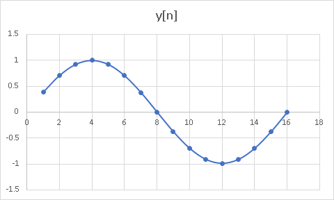
Here's a 16-point example with a table for the values that shows the terms needed for computing the output values and the total y[n] output for the filter. The sine output is the last column. The numbers with an exponent of E-15 or E-16 are essentially zero. All angles are in radians. Here are the constants for my example:
sin(Θ) = 0.3823864
r = 0.999, r^2 = 0.998001
2*r*cos(Θ) = 1.845911306
Below the table is a plot of the table points showing a sine wave.
| Point# | x[n] | sin(Θ)*x[n] | y[n-1] | y[n-2] | y[n]=Output |
| 1 | 1 | 0.382683432 | 0 | 0 | 0.382683432 |
| 2 | 0 | 0 | 0.382683432 | 0 | 0.706399674 |
| 3 | 0 | 0 | 0.706399674 | 0.382683432 | 0.922032697 |
| 4 | 0 | 0 | 0.922032697 | 0.706399674 | 0.997002999 |
| 5 | 0 | 0 | 0.997002999 | 0.922032697 | 0.920189554 |
| 6 | 0 | 0 | 0.920189554 | 0.997002999 | 0.703578311 |
| 7 | 0 | 0 | 0.703578311 | 0.920189554 | 0.380393064 |
| 8 | 0 | 0 | 0.380393064 | 0.703578311 | -8.88178E-16 |
| 9 | 0 | 0 | -8.88178E-16 | 0.380393064 | -0.3796326059 |
| 10 | 0 | 0 | -0.3796326059 | -8.88178E-16 | -0.700768217 |
| 11 | 0 | 0 | -0.700768217 | -0.3796326059 | -0.914682201 |
| 12 | 0 | 0 | -0.914682201 | -0.700768217 | -0.989054835 |
| 13 | 0 | 0 | -0.989054835 | -0.914682201 | -0.912853751 |
| 14 | 0 | 0 | -0.912853751 | -0.989054835 | -0.697969346 |
| 15 | 0 | 0 | -0.697969346 | -0.912853751 | -0.37736055 |
| 16 | 0 | 0 | -0.37736055 | -0.697969346 | 1.22125E-15 |
Here is the C-Code for the initialization of variables, called InitSine() and for the sine generation, called MakeSine().
/**********************************************************************
* Function: InitSine()
*
* Description: Initializes the sine wave generator algorithm
**********************************************************************/
void InitSine(void)
{
sine=0;
scale=0;
a= 0.049087385; /* a=sine(theta), theta = 2*pi/128 = 128 step sinewave */
b= 1.997590712; /* b=2*r*cos(theta) */
c= 0.999999800; /* c=r^2 */
x[0]=1;
x[1]=0;
y[0]=y[1]=y[2]=0;
sinindx = 0; /* Set the sine angle index counter to zero to initialize */
r=0; // r is the radius of the filter that approaches the unit circle but doesn't touch it.
} // end of InitSine function.
/**********************************************************************
* Function: MakeSine()
*
* Description: Computes the sine wave generator algorithm
**********************************************************************/
void MakeSine(void)
{
extern int PWM_qtr_period;
static Uint16 ebuf=0;
/* Sine Generation algorithm */
stepangle = _IQdiv(TWO_PI,Sinsteps);
angle = angle + stepangle;
if(angle >= (TWO_PI) )
{
angle = 0;
}
scale = TWO_PI+1;
sine = _IQsin(1.57079632);
angle = _IQsin(0.78539816);
waveformx0 = _IQsin(angle);
waveformx1 = _IQcos(angle);
// PWM_command1=(int)waveformx0;
// PWM_command2=(int)waveformx1;
/* Sine Generation algorithm */
if ((sinindx >=0) && (sinindx <= 63)) // First 64 Points of Sinewave.
{
Fout_squarewave1 = true;
}
else
{
Fout_squarewave1 = false;
}
if ((sinindx>=64) && (sinindx <= 127)) // 2nd 64 Points of Sinewave.
{
Fout_squarewave2 = true;
}
else
{
Fout_squarewave2 = false;
}
if (sinindx <= (Sinsteps - 1))
{
++sinindx; // increment sine step counter.
}
else
{
sinindx = 0;
}
if(sinindx == 0)
{
x[0]=1;
x[1]=0;
y[0]=y[1]=y[2]=0;
}
y[0]=a * x[1] + b * y[1] - c * y[2]; /* Equation that Computes the Sine Output */
sine =(int) Halfdacsize * y[0];
scale= Halfdacsize + sine;
x[1] = x[0]; /* Update the x & y arrays */
x[0] = 0;
y[2] = y[1];
y[1] = y[0];
} // end of MakeSine function.
_______________________________________________________________________________________
This code was actually used in a sine-wave inverter I designed to generate the sine reference for the PWM outputs.