

.jpg)

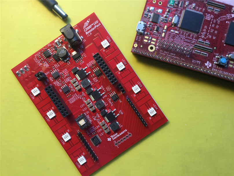
The TI LED BoosterPack has some interesting power devices. There's a Buck converter, a low drop linear regulator, a few Boost converters with power MOSFETs. The board also has 8 RGB power LEDs and current sensing circuits. Enough interesting electronics to investigate. In this first post, an overview
|
History
This is one of the lesser known BoosterPacks. It's marketed for the C2000 family, although it can be used by any 3.3 V development board. The only requirements are PWM and ADC capabilities.
I got his board from jc2048, in exchange for a dc:dc converter evaluation kit that I sent to him (little secret: several members on this community send each other their used kits).
I've been playing with this board and got it to work, but never blogged about it. In this series, I'm planning to review the modules on this board and do some measurements.
There's a User's Guide availabe, but no schematics - or even pin layout).
Part of the exercise will be to review the pins of the C2000 LaunchPad and derive the BoosterPack's pins from that. I'll also try to reverse-engineer some schematics where it helps.
Schematics are part of the controlSuite software that you can download, install and integrate in Code Composer Studio.
Modules
The board has a Buck converter to switch the 6 - 20 V power you supply to 5 V. That 5 V is then brought down to 3.3 V with a low drop linear regulator.
There are a few Boost converters to deliver enough voltage to drive a string of LEDs. These boost that same 6 - 20 V input up to to 24 V. They are controlled by a PWM signal that we have to provide externally.
Because the load is a string of LEDs that are current driven, there is a current sense circuit in each chain, consisting of a sense resistor and OpAmp. The results can be checked by an ADC.
What To Do?
Switch mode converters are interesting circuits. They are good candidates to validate your basic electroncs knowledge (capacitors, inductors, charges, current,...).
Whenever you feel rusty on your core electronics skills, try to do some switch mode converter analysis. You 'll need all of the things you learned early on about passive components. And you 'll refresh your semiconductor basics.
That's one of the reasons I pulled out this board. Give myself a challenge and recheck the things happening in each of these circuits.
There will be some firmware topics, mainly related to PWM, ADC and control theory (PID), early on . But that's not going to be the main focus.
That's just to have a working test bed, so that we can unleash the oscilloscope and multimeters. That's when the fun starts.
To keep my automotive skills current, I'll use a RM46 Hercules safety microcontroller as the logic core when needed.
Update: I killed the board. Magic smoke escaped... So no further updates.
Top Comments