element14 Community
element14 Community
    Register Log In
  • Site
  • Search
  • Log In Register
  • About Us
  • Community Hub
    Community Hub
    • What's New on element14
    • Feedback and Support
    • Benefits of Membership
    • Personal Blogs
    • Members Area
    • Achievement Levels
  • Learn
    Learn
    • Ask an Expert
    • eBooks
    • element14 presents
    • Learning Center
    • Tech Spotlight
    • STEM Academy
    • Webinars, Training and Events
    • Learning Groups
  • Technologies
    Technologies
    • 3D Printing
    • FPGA
    • Industrial Automation
    • Internet of Things
    • Power & Energy
    • Sensors
    • Technology Groups
  • Challenges & Projects
    Challenges & Projects
    • Design Challenges
    • element14 presents Projects
    • Project14
    • Arduino Projects
    • Raspberry Pi Projects
    • Project Groups
  • Products
    Products
    • Arduino
    • Avnet Boards Community
    • Dev Tools
    • Manufacturers
    • Multicomp Pro
    • Product Groups
    • Raspberry Pi
    • RoadTests & Reviews
  • Store
    Store
    • Visit Your Store
    • Choose another store...
      • Europe
      •  Austria (German)
      •  Belgium (Dutch, French)
      •  Bulgaria (Bulgarian)
      •  Czech Republic (Czech)
      •  Denmark (Danish)
      •  Estonia (Estonian)
      •  Finland (Finnish)
      •  France (French)
      •  Germany (German)
      •  Hungary (Hungarian)
      •  Ireland
      •  Israel
      •  Italy (Italian)
      •  Latvia (Latvian)
      •  
      •  Lithuania (Lithuanian)
      •  Netherlands (Dutch)
      •  Norway (Norwegian)
      •  Poland (Polish)
      •  Portugal (Portuguese)
      •  Romania (Romanian)
      •  Russia (Russian)
      •  Slovakia (Slovak)
      •  Slovenia (Slovenian)
      •  Spain (Spanish)
      •  Sweden (Swedish)
      •  Switzerland(German, French)
      •  Turkey (Turkish)
      •  United Kingdom
      • Asia Pacific
      •  Australia
      •  China
      •  Hong Kong
      •  India
      •  Korea (Korean)
      •  Malaysia
      •  New Zealand
      •  Philippines
      •  Singapore
      •  Taiwan
      •  Thailand (Thai)
      • Americas
      •  Brazil (Portuguese)
      •  Canada
      •  Mexico (Spanish)
      •  United States
      Can't find the country/region you're looking for? Visit our export site or find a local distributor.
  • Translate
  • Profile
  • Settings
Power & Energy
  • Technologies
  • More
Power & Energy
Forum LED Street Lighting Power supply
  • Blog
  • Forum
  • Quiz
  • Documents
  • Polls
  • Events
  • Mentions
  • Sub-Groups
  • Tags
  • More
  • Cancel
  • New
Actions
  • Share
  • More
  • Cancel
Forum Thread Details
  • Replies 27 replies
  • Subscribers 288 subscribers
  • Views 4982 views
  • Users 0 members are here
  • driver
  • lighting
  • led
  • supply
  • street
  • power
Related

LED Street Lighting Power supply

Jason
Jason over 15 years ago

Hello All,

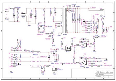
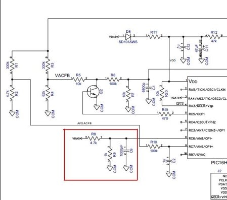
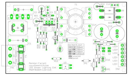
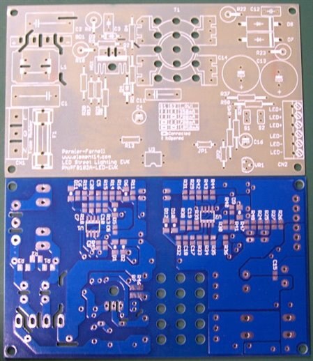
As we know, LED is used moreand more on street lighting, in the future, LED will replace the traditional street lighting bulb. Many supplier have there own power supply solution for LED street lighting, such as NXP, ON, PI,TI, Fairchild and so on, some solution is isolated Fly-back and some is non-isolated high voltage Buck to drive LED bulb, some solution use PFC controller and some use Valley PFC circuit to increase power factor. The question is which solution is more popular for the LED street lighting? isolated or non-isolated,  PFC controller or Valley PFC circuit?

  • Sign in to reply
  • Cancel
Parents
  • Jorge_Garcia
    Jorge_Garcia over 15 years ago

    Hi Jason,


    Hope you are doing well.


    I agree with Enrico in that you are better off using an active PFC based off a boost converter. The performance of the Valley Circuit is not going to be good enough for Street Lighting. However, I disagree with his recommendation of using an LLC resonant converter. The resonant converter topology is very common for Fluorescent Ballasts and the like however there's no need to go with such a sofisticated topology to drive LEDs.


    An active PFC gives a 400V rail, a well designed buck topology could be used to power the LEDs. The simplified conversion function for a buck controller is Vo=D*Vin the current relationship similarly is In=D*Io, I bring this up because even though the PFC stage stepped up the voltage the current you'll be able to draw from it won't be very great depending the Power output you have designed for. The buck topology takes in very little current for a given output current depending on the conversion ratio so it meshes very well with the PFC stage.


    I've designed drivers that make use of both the Buck and Boost topologies and they are simple to implement in an LED design. As Enrico mentioned these topologies are not isolated so if for safety reasons you must use an isolated supply then you may have to use one of the isolated topologies such as a Flyback. I mean no disrespect to Enrico his solution is valid, I just think it's more complicated then it needs to be.


    hth,


    Best Regards,


    Jorge Garcia

    Cadsoft Computer

    • Cancel
    • Vote Up 0 Vote Down
    • Sign in to reply
    • Cancel
  • enrico.migchels
    enrico.migchels over 15 years ago in reply to Jorge_Garcia

    Hi Jason,


    Ok, probably the active PFC and flyback is better . I have found an interesting article:


    http://powerelectronics.com/power_management/lighting_power_management/led-streetlight-high-brightness-0225/


    Jorge, we use LLC all the time :-) We like the EMI behaviour and the lack of stress on the power components. :-) Okay, you are the expert! ;-)


    Best regards, Enrico Migchels

    • Cancel
    • Vote Up 0 Vote Down
    • Sign in to reply
    • Cancel
  • Jason
    Jason over 15 years ago in reply to enrico.migchels

    Hi Enrico,

    The solution is wonderful, it is a singel stage topology but the controller is a MCU not the PFC controller. there is only primary detection, no secondary feedback. Use MCU can make the duty cycle accurately. But I have some questions:

    1,How to protect the driver when the secondary occur Over Voltage, Over Current, or Over Load?

    2,How to burn the code into the MCU, when the AC power is connect or not? If AC power is connect, how to isolated the ICSP Header and the AC input? If not, how to power the MCU?


    Jason

    • Cancel
    • Vote Up 0 Vote Down
    • Sign in to reply
    • Cancel
  • Jason
    Jason over 15 years ago in reply to firatkocak

    Hi Firat,

    What about you try,does it work well? I,m glad to hear about your experiment.

    Jason


    • Cancel
    • Vote Up 0 Vote Down
    • Sign in to reply
    • Cancel
  • Jorge_Garcia
    Jorge_Garcia over 15 years ago in reply to Jason

    Hi Jason,


    I hope you are doing well. I know this questions is for Enrico and I'm sure he'll chime in with his suggestions, but I'd like to take a crack at answering your questions.


    1.  I think Over voltage, Over Current, and Over load should be defined first. An over load will generally be caused by an over voltage fault or an overcurrent fault so you don't have to think about the over load as a seperate fault condition, if you take care of overvoltage and overcurrent conditions than the over load condition is also taken care of.


    Since your going to regulate current in the LEDs a short circuit condition will not be so bad. The flyback control loop will adjust the duty cycle in order to maintain a constant current, however you don't want the supply to stay in this condition for too long so once the condition is detected (say through a voltage divider across the output) then the MCU should shutdown the converter.


    An open circuit condition is far more serious because the control loop is trying to regulate current in an open circuit current can't flow to the sensing element (resistor, current transformer, etc.) so the control loop will continually increase the duty cycle to try to increase the current over time the the stress on the transistor and diode will become excessive and these components will be destroyed. The best way to handle this situation is to have a switchable load on the output ( the simplest example is a power resistor which is switch in on the low side with an NPN BJT or N channel FET) Once the open circuit condition is sensed then the MCU can activate the load across the output at which point current flow and the circuit can maintain regulation.


    2. Due to the low voltages and current needed by the MCU you'll generally have to make a secondary low power housekeeping supply and their are many ways to go about this. A few examples would be a bootstrap circuit , Auto oscillating buck converter, Royer converter, even a low power flyback would be suitable as a housekeeping supply.


    Most MCUs save program data in non-volatile EEPROM memory so you don't have to worry about losing your code once the power is removed.


    I hope this helps if you have any other questions please feel free to contact us.


    Best Regards,


    Jorge Garcia

    Cadsoft Computer

    • Cancel
    • Vote Up 0 Vote Down
    • Sign in to reply
    • Cancel
  • Jason
    Jason over 15 years ago in reply to Jorge_Garcia

    Thanks Jorge,

    It's very exciting that you replied.


    I do not know well how dose the MCU work.If I use a PFC controller for Single-stage Flyback application, I well set my OPP in primary, OVP and OCP in secondary. Generally,OPP is caused by an over voltage fault or an overcurrent fault,  the circuit will continued work untill some components are broken. It is necessary to setting OPP in primary to prevent broken the circuit .


    An open loop control is much difficult than closed-loop control. For open loop control, the contoller (no matter MCU or PFC IC) didn't know the situation of the output. But for closed-loop control, feedback signal will be detect by the controller.


    By the way, use MCU as the contoller is much expensive and complex than use PFC controller, and MCU is difficult to me, I don't know how to write the code, how to burn the code into the MCU. Use MCU, that means 'mission impossibility' image


    So, use PFC controller to finish this project is my decision. I find Fairchild's FAN7530 is suitable to my project.


    You can see my schematic circuit based on FAN7530 as follow.


    image

    • Cancel
    • Vote Up 0 Vote Down
    • Sign in to reply
    • Cancel
  • Jorge_Garcia
    Jorge_Garcia over 15 years ago in reply to Jason

    Hi Jason,


    I hope you are doing well.


    Don't worry you're not obligated to use an MCU.image


    You're on the right track, the only problem is that as it stands you have only made a Flyback converter, the chip itself is designed for Critical Conductin mode PFC not to run a Flyback.


    However from the brief look at the schematic you've given it seems like your trying to adapt it. If you've done this before than go with it, I'm just a little cautious because the chip isn't designed to run a Flyback but rather a boost PFC and I generally try to stick to manufacturer recommendations.


    In one of my earlier post I mentioned TI's LED cookbook which already contains some reference solutions to the driver your trying to create, so I hope you can take a little time to look it through, I think it will be well worth your time.


    hth,


    Jorge Garcia

    Cadsoft Computer

    • Cancel
    • Vote Up 0 Vote Down
    • Sign in to reply
    • Cancel
  • SmartEnergy
    SmartEnergy over 15 years ago in reply to Jason
    Microchip’s reference design actually is a closed-loop voltage control. Since secondary and aux coil has a fixed ratio, feedback input is sample from AUX. there is a note on PSR http://www.fairchildsemi.com/an/AN/AN-6067.pdf
    image
    • Cancel
    • Vote Up 0 Vote Down
    • Sign in to reply
    • Cancel
  • Jason
    Jason over 15 years ago in reply to Jorge_Garcia

    Hi Gorge,


    I thought it was a general flyback topology at the beginning, but in fact it is a single-stage Flyback which use PFC IC as its controller. They are similar but not same, you can see the capacitor C2 which is behind the bridge rectifier BD1, just 0.47uF, if it is a general flyback, C2's value must be over 68uF. We can see in the general flyback topology,the waveform on C2 is approximate DC but "m" type waveform in the single-stage Flyback topology. This is the ultimate differentia.


    Ti's solution is very good which use TPS92210, but apply the sample difficultly. I will use TI's reference design as my design resource


    Jason

    • Cancel
    • Vote Up 0 Vote Down
    • Sign in to reply
    • Cancel
  • Jason
    Jason over 15 years ago in reply to SmartEnergy

    Hi Hausa Lee,

    Thanks for you attention.

    I have seen many primary feedback applications such as cell phone charger, Li-on charger. But it always low power and low precision requirement. I don't konw if primary feedback suit to my project, I have set three type of output 350mA, 700mA and 1050mA, which have only +/-10% tolerance.


    Jason

    • Cancel
    • Vote Up 0 Vote Down
    • Sign in to reply
    • Cancel
  • Jason
    Jason over 15 years ago in reply to Jason

    Dear All,

    I 've accomplish my PCB design, it is single side layout and both side component placement.

    image

    Attachments:
    imageLED2.pdf
    imageLED1.pdf
    imageLED.pdf
    • Cancel
    • Vote Up 0 Vote Down
    • Sign in to reply
    • Cancel
  • Jason
    Jason over 15 years ago in reply to Jason

    I've received my PCB from the PCB maker and follow picture is it, very beautiful I think.

    image

    • Cancel
    • Vote Up 0 Vote Down
    • Sign in to reply
    • Cancel
Reply
  • Jason
    Jason over 15 years ago in reply to Jason

    I've received my PCB from the PCB maker and follow picture is it, very beautiful I think.

    image

    • Cancel
    • Vote Up 0 Vote Down
    • Sign in to reply
    • Cancel
Children
No Data
element14 Community

element14 is the first online community specifically for engineers. Connect with your peers and get expert answers to your questions.

  • Members
  • Learn
  • Technologies
  • Challenges & Projects
  • Products
  • Store
  • About Us
  • Feedback & Support
  • FAQs
  • Terms of Use
  • Privacy Policy
  • Legal and Copyright Notices
  • Sitemap
  • Cookies

An Avnet Company © 2025 Premier Farnell Limited. All Rights Reserved.

Premier Farnell Ltd, registered in England and Wales (no 00876412), registered office: Farnell House, Forge Lane, Leeds LS12 2NE.

ICP 备案号 10220084.

Follow element14

  • X
  • Facebook
  • linkedin
  • YouTube