element14 Community
element14 Community
    Register Log In
  • Site
  • Search
  • Log In Register
  • About Us
  • Community Hub
    Community Hub
    • What's New on element14
    • Feedback and Support
    • Benefits of Membership
    • Personal Blogs
    • Members Area
    • Achievement Levels
  • Learn
    Learn
    • Ask an Expert
    • eBooks
    • element14 presents
    • Learning Center
    • Tech Spotlight
    • STEM Academy
    • Webinars, Training and Events
    • Learning Groups
  • Technologies
    Technologies
    • 3D Printing
    • FPGA
    • Industrial Automation
    • Internet of Things
    • Power & Energy
    • Sensors
    • Technology Groups
  • Challenges & Projects
    Challenges & Projects
    • Design Challenges
    • element14 presents Projects
    • Project14
    • Arduino Projects
    • Raspberry Pi Projects
    • Project Groups
  • Products
    Products
    • Arduino
    • Avnet Boards Community
    • Dev Tools
    • Manufacturers
    • Multicomp Pro
    • Product Groups
    • Raspberry Pi
    • RoadTests & Reviews
  • Store
    Store
    • Visit Your Store
    • Choose another store...
      • Europe
      •  Austria (German)
      •  Belgium (Dutch, French)
      •  Bulgaria (Bulgarian)
      •  Czech Republic (Czech)
      •  Denmark (Danish)
      •  Estonia (Estonian)
      •  Finland (Finnish)
      •  France (French)
      •  Germany (German)
      •  Hungary (Hungarian)
      •  Ireland
      •  Israel
      •  Italy (Italian)
      •  Latvia (Latvian)
      •  
      •  Lithuania (Lithuanian)
      •  Netherlands (Dutch)
      •  Norway (Norwegian)
      •  Poland (Polish)
      •  Portugal (Portuguese)
      •  Romania (Romanian)
      •  Russia (Russian)
      •  Slovakia (Slovak)
      •  Slovenia (Slovenian)
      •  Spain (Spanish)
      •  Sweden (Swedish)
      •  Switzerland(German, French)
      •  Turkey (Turkish)
      •  United Kingdom
      • Asia Pacific
      •  Australia
      •  China
      •  Hong Kong
      •  India
      •  Korea (Korean)
      •  Malaysia
      •  New Zealand
      •  Philippines
      •  Singapore
      •  Taiwan
      •  Thailand (Thai)
      • Americas
      •  Brazil (Portuguese)
      •  Canada
      •  Mexico (Spanish)
      •  United States
      Can't find the country/region you're looking for? Visit our export site or find a local distributor.
  • Translate
  • Profile
  • Settings
Power & Energy
  • Technologies
  • More
Power & Energy
Forum Why is my LTC3780 only giving 0.8V - 2.8V output?
  • Blog
  • Forum
  • Quiz
  • Documents
  • Polls
  • Events
  • Mentions
  • Sub-Groups
  • Tags
  • More
  • Cancel
  • New
Actions
  • Share
  • More
  • Cancel
Forum Thread Details
  • State Not Answered
  • Replies 16 replies
  • Subscribers 287 subscribers
  • Views 2856 views
  • Users 0 members are here
  • lct3780
Related

Why is my LTC3780 only giving 0.8V - 2.8V output?

tim687
tim687 over 8 years ago

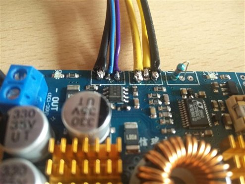
Recently I bought two of these, I was needed to remove all of the pots since they where bad. I soldered a resistor (500K) like this to the board to make sure that the undervoltage protection won't go off, since that was the issue I had when I powered up the board for the first time. That issue caused the fault led to light up and the output to not work.

I got one board working, since I wanted to get one working before I changed the other one. I am not sure if the resistor fix is correct here.

image


Now, a few days (maybe weeks further), I continued with the project and tried a reverse polarity protection circuit. That didn't work very well, but it was fun to see something, that is not supposed to light up, light up (@28.5V). Everything continued to work after the short!


The next day I soldered the banana plugs that came in to the output wires and all of a sudden the device wouldn't power more than around 2.8V. The fault led is lighting up and the chip is getting very hot.


Did I blew up the chip by testing out the lighting effects on components?


The strange thing is that, the other board isn't working at all. Same problem as the first one.

I didn't test the shortcut capabilities of the second board though.


I have ordered two new LTC3780's and a few of the LM358N's to make sure that they are all good.


I am doing anything wrong?

Attachments:
image
  • Sign in to reply
  • Cancel
Parents
  • tim687
    0 tim687 over 8 years ago

    According to the datasheet of the LTC3780 (G package).

    Here are the voltages


    Pin:

    1: 8.89V

    2: 5.30V

    3: 0.18V (at lowest and highest voltage output setting)

    4: 0.18V

    5: 0.32V at lowest output and ~ 2 V at highest output

    6: 0.80 V at lowest and 0.08V at highest output

    7: 0 V

    8: ~ 9.2 V

    9: 0 V

    10: 1.53 V

    11: 0 V

    12: 1 V

    13: 6.42 V at lowest and 7.84 V at highest

    14: 1.12 V (lowest) ~ 3.45V (highest)

    15: 0.80 V (lowest) ~ 2.80V (highest)

    16: 5.84 V (lowest) ~ 1.18V (highest)

    17: 0V

    18: 0.06 V (lowest) ~0.12V (highest)

    19: 5.95 V

    20: 0 V

    21: 12 V (lowest = input voltage) ~ 3.80 V (highest)

    22: 0.77 V (lowest) ~ 2.00V (highest)

    23: 5.60 V (lowest) ~ 0.90 V (highest)

    24: 5.63 V (lowest) ~ 7.30 V (highest)

    • Cancel
    • Vote Up 0 Vote Down
    • Sign in to reply
    • Verify Answer
    • Cancel
  • michaelkellett
    0 michaelkellett over 8 years ago in reply to tim687

    I don't quite understand what lines like this mean:


    21: 12 V (lowest = input voltage) ~ 3.80 V (highest)


    this is the power input - it should be constant


    The voltage on pin 8 looks like a serious fault - but it has that ~ again and I don't know what it means.


    What is connected to pin 8 - it should be a steady 0V or 5V  - I really need a full schematic to help properly.


    From the history it looks as if something has blown but I can't tell what.


    It is very ambitious to try to debug a switching power supply when you don't have access to a scope - can you borrow one ?


    MK

    • Cancel
    • Vote Up 0 Vote Down
    • Sign in to reply
    • Verify Answer
    • Cancel
  • tim687
    0 tim687 over 8 years ago in reply to michaelkellett

    21: 12 V (lowest = input voltage) ~ 3.80 V (highest)


    At the lowest output voltage selected, that line is 12 V.

    At the highest output voltage selected, it is around 3.80 V


    I do have access to a scope, but then I don't have access to my own gear.


    The chip get's very hot when I put the output voltage at max.

    • Cancel
    • Vote Up 0 Vote Down
    • Sign in to reply
    • Verify Answer
    • Cancel
  • michaelkellett
    0 michaelkellett over 8 years ago in reply to tim687

    Well, if Vin is collapsing it suggests a huge current - what is the power supply ?

    The fact that the current is affected when the demand for output volts is altered suggests that the 3780 is trying to work.

    It could be that the 3780 is faulty or it could be one of the MOSFETs (or both).

    You could remove the 3780 and test the MOSFETs in place.


    MK

    • Cancel
    • Vote Up 0 Vote Down
    • Sign in to reply
    • Verify Answer
    • Cancel
Reply
  • michaelkellett
    0 michaelkellett over 8 years ago in reply to tim687

    Well, if Vin is collapsing it suggests a huge current - what is the power supply ?

    The fact that the current is affected when the demand for output volts is altered suggests that the 3780 is trying to work.

    It could be that the 3780 is faulty or it could be one of the MOSFETs (or both).

    You could remove the 3780 and test the MOSFETs in place.


    MK

    • Cancel
    • Vote Up 0 Vote Down
    • Sign in to reply
    • Verify Answer
    • Cancel
Children
  • tim687
    0 tim687 over 8 years ago in reply to michaelkellett

    Unfortunately, the mosfets are covered with a heatsink.


    The power supply is a 600W server psu.

    The board receives 12V from the psu and when I turned the output voltage to max voltage, the extra current draw was 100mA at max.

    • Cancel
    • Vote Up 0 Vote Down
    • Sign in to reply
    • Verify Answer
    • Cancel
  • michaelkellett
    0 michaelkellett over 8 years ago in reply to tim687

    Some designs have  a resistor between Vin and pin 21 which would explain why the voltage is dropping at that point and your power supply is still alive.


    If you take the 3780 off you can test the MOSFETS from its pads without taking the heatsink off.


    Put a 100R resistor between that 600W supply and the board while you are testing them.


    MK

    • Cancel
    • Vote Up 0 Vote Down
    • Sign in to reply
    • Verify Answer
    • Cancel
  • tim687
    0 tim687 over 8 years ago in reply to michaelkellett

    How do I test the mosfets exactly?


    The 100R resistor is preventing huge current flows I suppose?

    • Cancel
    • Vote Up 0 Vote Down
    • Sign in to reply
    • Verify Answer
    • Cancel
element14 Community

element14 is the first online community specifically for engineers. Connect with your peers and get expert answers to your questions.

  • Members
  • Learn
  • Technologies
  • Challenges & Projects
  • Products
  • Store
  • About Us
  • Feedback & Support
  • FAQs
  • Terms of Use
  • Privacy Policy
  • Legal and Copyright Notices
  • Sitemap
  • Cookies

An Avnet Company © 2025 Premier Farnell Limited. All Rights Reserved.

Premier Farnell Ltd, registered in England and Wales (no 00876412), registered office: Farnell House, Forge Lane, Leeds LS12 2NE.

ICP 备案号 10220084.

Follow element14

  • X
  • Facebook
  • linkedin
  • YouTube