hello,
let's start saying i am not an engineer, i hope that this will save me if i say something too dumb
so, this is a general discussion about possible approaches in circuit protection (from the hobbist point of view, so please try to keep it simple) in DC circuits, the main goals for me are simplicity, low cost and low number of components.
I have many doubts that i hope you could help me to solve. I will start saying what i know, this will be very useful for me, if i write something wrong please correct me 
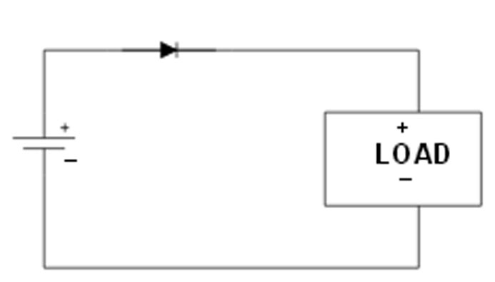
reverse voltage protection:
rectifier diode: this is the simplest one, i think that the only problem is the voltage drop across the diode and the power dissipation, or there are other cons?
schotty diode: same circuit as before, but with lower voltage drop and power dissipation but there is a problem more, them have a bigger reverse leakage current compared to
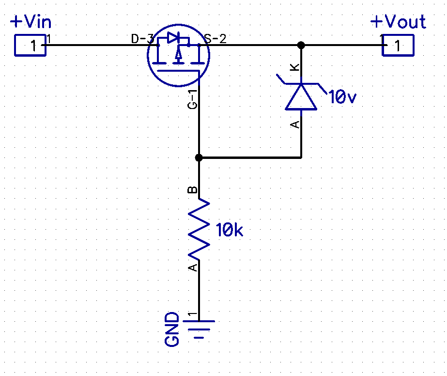
mosfet: this should be the best solution about power dissipation but i would need 2 components more
bjt: similar to the mosfet but with only a component more compared to the diode, or there are other difference?

about protection, without considering the power loss are them all the same?
over current protection:
Fuses: its simple and it work every time, isn't it?

bjt: i didn't find many information on this

well really i doesn't know any other simple techniques, but as soon the fuses work well isn't it a problem, or not?
over voltage protection:
i was going to write about a few techniques but this article is very good and simple: https://www.electronics-notes.com/articles/analogue_circuits/power-supply-electronics/over-voltage-protection.php
SCR: i am not familiar with these diodes and i would rather to not uses them since i have plenty of other kind of diodes home and i wouldn't like to buy others 

Zener diode: when the voltage exceed the rated maximum breakdown voltage it will protect my circuit creating a short circuit, right?
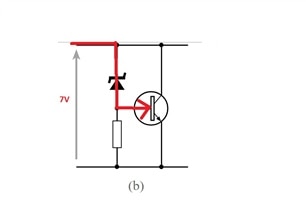
which is the difference between (a) and (b) only that the last one can handle more current?

referring to circuit (a) there is something i don't understand, if i create a short circuit isn't this bad? shouldn't i need to put a load (i.e. a resistor) in series with the zener?
while in (b) i will try to explain how it works (i learned how transistor works only a few weeks ago):
if the voltage doesn't exceed the breakdown voltage the npn is pull-down by the resistor so it's open. otherwise if the voltage is too high the bjt will be pulled-up and the circuit close creating a short circuit
same as before, isn't a short circuit bad?
i hope someone will find the time to answer to some of this doubts, even if you can answer only to a few of them for me it would be very usefull!