element14 Community
element14 Community
    Register Log In
  • Site
  • Search
  • Log In Register
  • About Us
  • Community Hub
    Community Hub
    • What's New on element14
    • Feedback and Support
    • Benefits of Membership
    • Personal Blogs
    • Members Area
    • Achievement Levels
  • Learn
    Learn
    • Ask an Expert
    • eBooks
    • element14 presents
    • Learning Center
    • Tech Spotlight
    • STEM Academy
    • Webinars, Training and Events
    • Learning Groups
  • Technologies
    Technologies
    • 3D Printing
    • FPGA
    • Industrial Automation
    • Internet of Things
    • Power & Energy
    • Sensors
    • Technology Groups
  • Challenges & Projects
    Challenges & Projects
    • Design Challenges
    • element14 presents Projects
    • Project14
    • Arduino Projects
    • Raspberry Pi Projects
    • Project Groups
  • Products
    Products
    • Arduino
    • Avnet Boards Community
    • Dev Tools
    • Manufacturers
    • Multicomp Pro
    • Product Groups
    • Raspberry Pi
    • RoadTests & Reviews
  • Store
    Store
    • Visit Your Store
    • Choose another store...
      • Europe
      •  Austria (German)
      •  Belgium (Dutch, French)
      •  Bulgaria (Bulgarian)
      •  Czech Republic (Czech)
      •  Denmark (Danish)
      •  Estonia (Estonian)
      •  Finland (Finnish)
      •  France (French)
      •  Germany (German)
      •  Hungary (Hungarian)
      •  Ireland
      •  Israel
      •  Italy (Italian)
      •  Latvia (Latvian)
      •  
      •  Lithuania (Lithuanian)
      •  Netherlands (Dutch)
      •  Norway (Norwegian)
      •  Poland (Polish)
      •  Portugal (Portuguese)
      •  Romania (Romanian)
      •  Russia (Russian)
      •  Slovakia (Slovak)
      •  Slovenia (Slovenian)
      •  Spain (Spanish)
      •  Sweden (Swedish)
      •  Switzerland(German, French)
      •  Turkey (Turkish)
      •  United Kingdom
      • Asia Pacific
      •  Australia
      •  China
      •  Hong Kong
      •  India
      •  Korea (Korean)
      •  Malaysia
      •  New Zealand
      •  Philippines
      •  Singapore
      •  Taiwan
      •  Thailand (Thai)
      • Americas
      •  Brazil (Portuguese)
      •  Canada
      •  Mexico (Spanish)
      •  United States
      Can't find the country/region you're looking for? Visit our export site or find a local distributor.
  • Translate
  • Profile
  • Settings
Power & Energy
  • Technologies
  • More
Power & Energy
Forum Looking for a specific type of pot/variable resistor
  • Blog
  • Forum
  • Quiz
  • Documents
  • Polls
  • Events
  • Mentions
  • Sub-Groups
  • Tags
  • More
  • Cancel
  • New
Actions
  • Share
  • More
  • Cancel
Forum Thread Details
  • State Suggested Answer
  • Replies 15 replies
  • Answers 11 answers
  • Subscribers 288 subscribers
  • Views 2504 views
  • Users 0 members are here
  • rheostat
  • potentiometer
  • rotary
  • pot
  • variable resistor
  • resistor
Related

Looking for a specific type of pot/variable resistor

damonjohn20
damonjohn20 over 6 years ago

Hi,


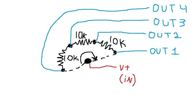
I'm new to this site so I may be posting this question in the wrong location. I'm looking for a specific type of variable resistor, in my research I haven't been able to discover something that fits this description (probably due to my lack of industry knowledge and associated vocabulary). Considering that a regular 3 pin 10k pot has one common pin (pin 2) and 2 'output' pins (pins 1 and 3), the resistance between pins 1 and 2 + the resistance between pins 2 and 3 will always add up to 10k. I'm looking for something similar, but with 4 or 5 output pins, while still keeping the singular common pin. I drew a very crude diagram of the general idea of what I'm looking for. image


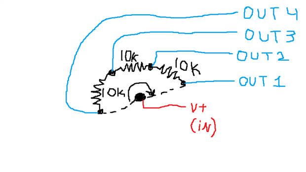
In the center of the semi-circle, this represents my common pin (preferably on a rotary) that adjusts the voltage across 4 output terminals.


If anyone knows the name of this type of component, I could figure out where to start in my research for the right one.


Thanks in advance.

  • Sign in to reply
  • Cancel

Top Replies

  • jw0752
    jw0752 over 6 years ago in reply to damonjohn20 +5 suggested
    Hi Damon, As promised I have used the special potentiometer that I found to prove that your idea for a potentiometer that can turn on different banks of LEDs as it is rotated is a viable idea. In this…
  • jw0752
    jw0752 over 6 years ago in reply to damonjohn20 +4 suggested
    Most potentiometers are not designed to handle power. You might get by with one or two LEDs but as soon as you try to handle more than this the pot will over heat and burn up. What you are describing will…
  • jw0752
    jw0752 over 6 years ago +3 suggested
    Hi Again Damon, For the fun of it I checked my stock and found this curiosity: This is a 3 gang potentiometer with one independent 1 meg gang at the front and two mechanically locked 425K gangs at the…
  • jw0752
    0 jw0752 over 6 years ago

    Hi Damon,


    Your picture/drawing did not come through so I am not sure this will answer your question but potentiometers are available in a dual configuration. Check out this one from Newark:


    https://www.newark.com/citec-te-connectivity/27esa103mmf50nf/potentiometer-d-gang-linear-10kohm/dp/26M6980?st=citec%20te


    The center wiper can be tied together and then there will be five contacts. I am not familiar with a circuit where this might be useful but perhaps you can give us some more information on your application.


    I have over the years also seen potentiometers with taps in the resistance that adds extra contacts but these are quite rare and may only be available as special OEM parts.


    If you can find a way to load your drawing using the picture upload icon on the tool bar we can give you further information.


    John

    • Cancel
    • Vote Up +1 Vote Down
    • Sign in to reply
    • Verify Answer
    • Reject Answer
    • Cancel
  • damonjohn20
    0 damonjohn20 over 6 years ago in reply to jw0752

    Thanks for the fast response. My application is for an RBG light strip. Ignoring the RGBW option, one of these strips has 4 pins on its connector. One of the pins is 12V+, and the other 3 are the ground pins for each respective color. I'll try including the picture in a different format below.

    image

    Assuming this potentiometer has 4 pins and rotates 360deg, at 0deg it would ground the red diodes. At 180deg, it would ground the blue diodes, and at 360deg it would ground the green diodes. With this setup, I would be able to rotate the pot into any position I would like, granting me any color of the rainbow based on it's position. **my diagram has 5 pins, not 4, but same concept


    Should I start looking into a different way to accomplish this? Such as using a fet for each color channel?

    • Cancel
    • Vote Up +1 Vote Down
    • Sign in to reply
    • Verify Answer
    • Reject Answer
    • Cancel
  • jw0752
    0 jw0752 over 6 years ago

    Hi Again Damon,


    For the fun of it I checked my stock and found this curiosity:


      imageimage


    This is a 3 gang potentiometer with one independent 1 meg gang at the front and two mechanically locked 425K gangs at the back. Each of the 425K gangs has a tap at 150K from each end with a net 125K  between the taps. If you happen to need one potentiometer like this one I will give you my address. If you need more than one you are out of luck as I probably salvaged it 40 years ago from an old TV and it is the only one like it that I have seen.


    I am really curious what type of circuit would need a control like this.


    John

    • Cancel
    • Vote Up +3 Vote Down
    • Sign in to reply
    • Verify Answer
    • Reject Answer
    • Cancel
  • jw0752
    0 jw0752 over 6 years ago in reply to damonjohn20

    Most potentiometers are not designed to handle power. You might get by with one or two LEDs but as soon as you try to handle more than this the pot will over heat and burn up. What you are describing will be best handled with a micro computer like an arduino and some MOSFETs to drive the LEDs. You could still use a potentiometer to control which LEDs are lit and how bright they are. The Arduino would read the potentiometer and translate its position into your desired configuration of lights and intensities. If you haven't worked with Arduinos before your application is a good pretext to start.


    John

    • Cancel
    • Vote Up +4 Vote Down
    • Sign in to reply
    • Verify Answer
    • Reject Answer
    • Cancel
  • jw0752
    0 jw0752 over 6 years ago in reply to damonjohn20

    Check out Jeremy Blum's book Exploring Arduino  Chapters 1 through 3 will likely give you all you need to know to accomplish what you are describing.


    https://www.exploringarduino.com/content/


    John

    • Cancel
    • Vote Up +3 Vote Down
    • Sign in to reply
    • Verify Answer
    • Reject Answer
    • Cancel
  • luislabmo
    0 luislabmo over 6 years ago in reply to jw0752

    Well my understanding is, he wants to try the colors of the rainbow with an RGB strip with just 1 pot turn, the problem I see this requires a tailor made pot for that, the other problem I see is some colors of the rainbow require a mix of all 3 channels (like the orange), and I'm not sure whether he is trying to do that directly connecting the pot to the RGB strip which is a completely different problem.


    Luis

    • Cancel
    • Vote Up +3 Vote Down
    • Sign in to reply
    • Verify Answer
    • Reject Answer
    • Cancel
  • luislabmo
    0 luislabmo over 6 years ago in reply to damonjohn20

    Hello Damon,


    Few observations:

    • If trying to control the RGB strip by directly connecting a potentiometer to it, this is not a good approach
    • If trying to reproduce just the colors of the rainbow with a turn of a pot probably you will be fine just with a pot, 3 MOSFETS and help of some PWM but, if you are trying to get any RGB combination, there is no way to accomplish this since we are talking about a 3-dimensional setting and a pot will give you a 2-dimentional value; If using a pot with more pins, well probably not every 3-value combination can be achieved.
    • My suggestion is to explore a FET option, probably this is what you are looking for
    • Another thing you may try -if absolutely want to do something with just 1 turn (or many turns) of a thing- is, try exploring a rotary encoder, these are nice, and in some applications better than pots because you can get stable and accurate values at any given time.
    • An ultimate option may be, trying an App that can allow you to pick any RGB color from a palette, here is one and another one.


    Luis

    • Cancel
    • Vote Up +3 Vote Down
    • Sign in to reply
    • Verify Answer
    • Reject Answer
    • Cancel
  • damonjohn20
    0 damonjohn20 over 6 years ago in reply to jw0752

    In response to John and Luis both (not sure how to respond to both at once)


    Thanks for all your input, I have definitely worked with microcontrollers before, but was looking to simplify the schematic by avoiding the logical processing all together. Unfortunately I don't have the knowledge or experience (yet) to know the solutions that are or aren't available, hence this post!


    Based on all of this, it's definitely looking like I'm going to have to go with the microcontroller route. Your find of that unique pot is very interesting, I've definitely never been aware of any product that has a dual function rotary pot such as that one.


    Luis nailed it in saying that my pot concept wouldn't have touched on every RGB color combination possible. Assuming I was working with a single low power LED, I'd be interested to see if some combination of a pot like I drew and a few 10k resistors across the output pins could provide a desired result.


    Thanks again


    Damon

    • Cancel
    • Vote Up +3 Vote Down
    • Sign in to reply
    • Verify Answer
    • Reject Answer
    • Cancel
  • jw0752
    0 jw0752 over 6 years ago in reply to damonjohn20

    Tonight for the fun of it I will breadboard up a circuit to do what you describe, using the odd potentiometer that I have. We will see how it works out.

    John

    • Cancel
    • Vote Up +2 Vote Down
    • Sign in to reply
    • Verify Answer
    • Reject Answer
    • Cancel
  • jw0752
    0 jw0752 over 6 years ago in reply to damonjohn20

    Hi Damon,


    As promised I have used the special potentiometer that I found to prove that your idea for a potentiometer that can turn on different banks of LEDs as it is rotated is a viable idea. In this circuit I am only turning on one small LED for each bank but depending on the MOSFETs and how they are heat sunk you could potentially turn on fairly high wattage. I have used 6 volts to power the circuit as this was the optimal voltage to make a good demonstration. We could have gone to 12 volts but then I would have had to adjust the resistor dividers so that I could get the same control and effect. There is also no reason why the drain - source circuit could not be powered with 12 or higher voltage and leave the potentiometer gate circuit at 6 volts. Here is a schematic for the circuit that you described:


    image


    I have also made a short video to demonstrate the operation. I know that it isn't exactly the fade between colors that you were seeking but if I were to put a tricolor LED in place of three of the LEDs we would see some of the fade between color effect.


    You don't have permission to edit metadata of this video.
    Edit media
    x
    image
    Upload Preview
    image


    While the video loaded up I went back and added a RGB Common Anode LED to three of the MOSFETs and it did as expected and faded from one color into the next color though Green White Purple Red and all the shades in between.


    John

    • Cancel
    • Vote Up +5 Vote Down
    • Sign in to reply
    • Verify Answer
    • Reject Answer
    • Cancel
>
element14 Community

element14 is the first online community specifically for engineers. Connect with your peers and get expert answers to your questions.

  • Members
  • Learn
  • Technologies
  • Challenges & Projects
  • Products
  • Store
  • About Us
  • Feedback & Support
  • FAQs
  • Terms of Use
  • Privacy Policy
  • Legal and Copyright Notices
  • Sitemap
  • Cookies

An Avnet Company © 2025 Premier Farnell Limited. All Rights Reserved.

Premier Farnell Ltd, registered in England and Wales (no 00876412), registered office: Farnell House, Forge Lane, Leeds LS12 2NE.

ICP 备案号 10220084.

Follow element14

  • X
  • Facebook
  • linkedin
  • YouTube