element14 Community
element14 Community
    Register Log In
  • Site
  • Search
  • Log In Register
  • Community Hub
    Community Hub
    • What's New on element14
    • Feedback and Support
    • Benefits of Membership
    • Personal Blogs
    • Members Area
    • Achievement Levels
  • Learn
    Learn
    • Ask an Expert
    • eBooks
    • element14 presents
    • Learning Center
    • Tech Spotlight
    • STEM Academy
    • Webinars, Training and Events
    • Learning Groups
  • Technologies
    Technologies
    • 3D Printing
    • FPGA
    • Industrial Automation
    • Internet of Things
    • Power & Energy
    • Sensors
    • Technology Groups
  • Challenges & Projects
    Challenges & Projects
    • Design Challenges
    • element14 presents Projects
    • Project14
    • Arduino Projects
    • Raspberry Pi Projects
    • Project Groups
  • Products
    Products
    • Arduino
    • Avnet Boards Community
    • Dev Tools
    • Manufacturers
    • Multicomp Pro
    • Product Groups
    • Raspberry Pi
    • RoadTests & Reviews
  • Store
    Store
    • Visit Your Store
    • Choose another store...
      • Europe
      •  Austria (German)
      •  Belgium (Dutch, French)
      •  Bulgaria (Bulgarian)
      •  Czech Republic (Czech)
      •  Denmark (Danish)
      •  Estonia (Estonian)
      •  Finland (Finnish)
      •  France (French)
      •  Germany (German)
      •  Hungary (Hungarian)
      •  Ireland
      •  Israel
      •  Italy (Italian)
      •  Latvia (Latvian)
      •  
      •  Lithuania (Lithuanian)
      •  Netherlands (Dutch)
      •  Norway (Norwegian)
      •  Poland (Polish)
      •  Portugal (Portuguese)
      •  Romania (Romanian)
      •  Russia (Russian)
      •  Slovakia (Slovak)
      •  Slovenia (Slovenian)
      •  Spain (Spanish)
      •  Sweden (Swedish)
      •  Switzerland(German, French)
      •  Turkey (Turkish)
      •  United Kingdom
      • Asia Pacific
      •  Australia
      •  China
      •  Hong Kong
      •  India
      •  Korea (Korean)
      •  Malaysia
      •  New Zealand
      •  Philippines
      •  Singapore
      •  Taiwan
      •  Thailand (Thai)
      • Americas
      •  Brazil (Portuguese)
      •  Canada
      •  Mexico (Spanish)
      •  United States
      Can't find the country/region you're looking for? Visit our export site or find a local distributor.
  • Translate
  • Profile
  • Settings
Power & Energy
  • Technologies
  • More
Power & Energy
Forum ClassD amplifier for transformer
  • Blog
  • Forum
  • Quiz
  • Documents
  • Polls
  • Events
  • Mentions
  • Sub-Groups
  • Tags
  • More
  • Cancel
  • New
Actions
  • Share
  • More
  • Cancel
Forum Thread Details
  • State Suggested Answer
  • Replies 8 replies
  • Answers 2 answers
  • Subscribers 285 subscribers
  • Views 2437 views
  • Users 0 members are here
  • classd
  • classab
Related

ClassD amplifier for transformer

hasan2015
hasan2015 over 5 years ago

Hi,

Hope this post find you well.

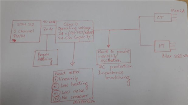
My intention is to make an 3-phase power calibrator !

image

Similar to this link, https://us.flukecal.com/products/ele...wer-calibrator


My current AMP design might be class AB type.


I am not worried to much about PWM generation ruther I am thinking how can I move class AB to Class D amplification.

A lot of the design effort relates to maintaining linearity and avoiding crossover distortion.

2  amplifiers( current, voltage)  output will feed to CT and PT! Lets consider load will be connected in their output!


REQUIRMENTS :


1. The amp input  should be  plus and minus 7volt AC, 45-65Hz( 1 Hz has been converted to 1024)

2. Amp operating voltage should be more or less 24v.

3. 2 channel signal (not sure PWM) should be use , one for current, one for voltage.

4.Can run current transformer(input 16.5 V/1.5 A)  and potential Transformer (input15v/2A). PT output may be 15VAC.

5. If possible both voltage and current amplification is required in one IC.

6. Both positive and negative half signal should be amplify

  • Sign in to reply
  • Cancel

Top Replies

  • michaelkellett
    michaelkellett over 5 years ago +4 suggested
    TI make a range of class D switching amplifiers which could be used for your application. The TPA3245 looks quite a good fit for your application - more power than you need so much less likely to fail…
  • hasan2015
    hasan2015 over 5 years ago in reply to michaelkellett +1
    Dear Sir Michael, Thnak you to respond here. I am also looking for TI IC's. For sure I will check out TPA3245. Now the main issue is,,, 1. Low frequency and high frequency phase shifts caused by a transformer…
  • michaelkellett
    michaelkellett over 5 years ago in reply to hasan2015 +1
    If your primary impedance is 0.0017R then you have the wrong transformer. The TPA3245 will give optimum performance with a load in the impedance range 3 - 15R, you'll get best efficiency with half bridge…
  • michaelkellett
    0 michaelkellett over 5 years ago

    TI make a range of class D switching amplifiers which could be used for your application.


    The TPA3245 looks quite a good fit for your application - more power than you need so much less likely to fail.

    You'll need extra protection in case the transformer  load is suddenly disconnected.


    MK

    • Cancel
    • Vote Up +4 Vote Down
    • Sign in to reply
    • Verify Answer
    • Reject Answer
    • Cancel
  • hasan2015
    0 hasan2015 over 5 years ago in reply to michaelkellett

    Dear Sir Michael,


    Thnak you to respond here.

    I am also looking for TI IC's.


    For sure I will check out TPA3245.

    Now the main issue is,,,


    1. Low frequency and high frequency phase shifts caused by a transformer will occur if the transformer is inside the negative feedback loop (when the output of the transformer provides the negative feedback). Then the amplifier must be compensated for these phase shifts.


    2.  A product with a Class-D audio power amplifier (APA) driving an output transformer with inadequate low-frequency performance may shut down when its output is stepped from zero to maximum at the start of a sine cycle. Shutdown is triggered by short circuit protection (SCP), after the first half cycle of the sine output. The root cause is saturation of the transformer core.


    • Cancel
    • Vote Up +1 Vote Down
    • Sign in to reply
    • Verify Answer
    • Cancel
  • michaelkellett
    0 michaelkellett over 5 years ago in reply to hasan2015

    Don't even think about putting the transformer in the feedback loop of a single chip class D amplifier - it wasn't designed for this and you will never get is to be stable.

    You can still compensate for transformer losses by monitoring the output side of the system, or possibly by feedback windings on the transformer - but you will need to accept control of average amplitude rather than instantaneous.


    Your second problem can be dealt with by ramping the sine wave amplitude.


    MK

    • Cancel
    • Vote Up 0 Vote Down
    • Sign in to reply
    • Verify Answer
    • Reject Answer
    • Cancel
  • hasan2015
    0 hasan2015 over 5 years ago in reply to michaelkellett
    Don't even think about putting the transformer in the feedback loop of a single chip class D amplifier - it wasn't designed for this and you will never get is to be stable.


    Looking at your suggested TPA3245 evm board,

    image


    How would you connect such 60Hz step up transformer ?

    Should it  be H-bridge or BTL !!


    LC filter is visible here! in my case the primary side impedance is 0.00117ohm.

    People says , Audio amp can usable for 2- 16ohm load!

    While it was connected to Class A output , a 10 ohm along with 0.33uF in series RC filter was connected parallay to primary.

    Looking at the datasheet "Signal Bandwidth up to 100 kHz for High Frequency Content From HD Sources "


    does it compatible ?

    • Cancel
    • Vote Up 0 Vote Down
    • Sign in to reply
    • Verify Answer
    • Cancel
  • michaelkellett
    0 michaelkellett over 5 years ago in reply to hasan2015

    If your primary impedance is 0.0017R then you have the wrong transformer.


    The TPA3245 will give optimum performance with a load in the impedance range 3 - 15R, you'll get best efficiency with half bridge and paralleled outputs (if the chip supports this mode.) or BTL.


    (Note: 7V AC which you mention in your original posting into 0.00117R = 41.8kW, but with 10R series resistor only 0.0006W would get into the load - I think your calculations are wrong somewhere,)


    How much power do you actually want to put into the load, and what is the load impedance.


    MK

    • Cancel
    • Vote Up +1 Vote Down
    • Sign in to reply
    • Verify Answer
    • Cancel
  • hasan2015
    0 hasan2015 over 5 years ago in reply to michaelkellett
    If your primary impedance is 0.0017R then you have the wrong transformer


    Sorry It was just primary winding resistance.

    0.00117ohm is a dead short. An audio amplifier is designed to drive 4 ohms to 16 ohms.

    The transformer is 15V with a current of 2A then its impedance is 7.5 ohms.

    While it was connected to Class AB output , a 10 ohm along with 0.33uF in series RC grounded filter was connected parallay to its primary.


    The TPA3245 will give optimum performance with a load in the impedance range 3 - 15R, you'll get best efficiency with half bridge and paralleled outputs (if the chip supports this mode.) or BTL

    I think this user has some  similar problem, https://e2e.ti.com/support/audio/f/6/t/483271

    • Cancel
    • Vote Up 0 Vote Down
    • Sign in to reply
    • Verify Answer
    • Cancel
  • michaelkellett
    0 michaelkellett over 5 years ago in reply to hasan2015

    Check out the other amps in the TI range - your simplest option is to use single ended mode (only one output series cap needed) but you need a chip where you can have one output made by running two or more in //.


    I don't think you will get the BTL configuration to have a low enough offset.


    MK

    • Cancel
    • Vote Up 0 Vote Down
    • Sign in to reply
    • Verify Answer
    • Cancel
  • hasan2015
    0 hasan2015 over 5 years ago in reply to michaelkellett
    I don't think you will get the BTL configuration to have a low enough offset.

    Driving CT is a problem because ClassD is a voltage source.

    Some one said for this application,

    "class-D audio amplifier IC is smart. It has current limiting and high temperature shut-down.

    But for your electrical application you probably want to select the amount of voltage produced by your current transformer and its shunt resistance.

    So select a class-D amplifier IC that produces more current than you need and connect your shunt resistor to its negative feedback input if it has one."


    How about use UCX637 DC motor controller for this issue ?


    image


    Idea covers here ,https://www.thierry-lequeu.fr/data/SLUA137.pdf

    • Cancel
    • Vote Up 0 Vote Down
    • Sign in to reply
    • Verify Answer
    • Cancel
element14 Community

element14 is the first online community specifically for engineers. Connect with your peers and get expert answers to your questions.

  • Members
  • Learn
  • Technologies
  • Challenges & Projects
  • Products
  • Store
  • About Us
  • Feedback & Support
  • FAQs
  • Terms of Use
  • Privacy Policy
  • Legal and Copyright Notices
  • Sitemap
  • Cookies

An Avnet Company © 2025 Premier Farnell Limited. All Rights Reserved.

Premier Farnell Ltd, registered in England and Wales (no 00876412), registered office: Farnell House, Forge Lane, Leeds LS12 2NE.

ICP 备案号 10220084.

Follow element14

  • X
  • Facebook
  • linkedin
  • YouTube