Good morning. First-time newbie here. 2 years ago I yanked all the fluorescent fixtures from my shop and replaced them with LED strips, powered by cheap Chinese power supplies, see below (120VAC>12VDC, 30A).
Some have begun to fail, and so I bought some new ones - exact replacements - and am using one as a standard against which to compare values, and help deduce faulty components. (not that I don’t have some clear “winners” already, i. e. swollen caps, blown thermistors).
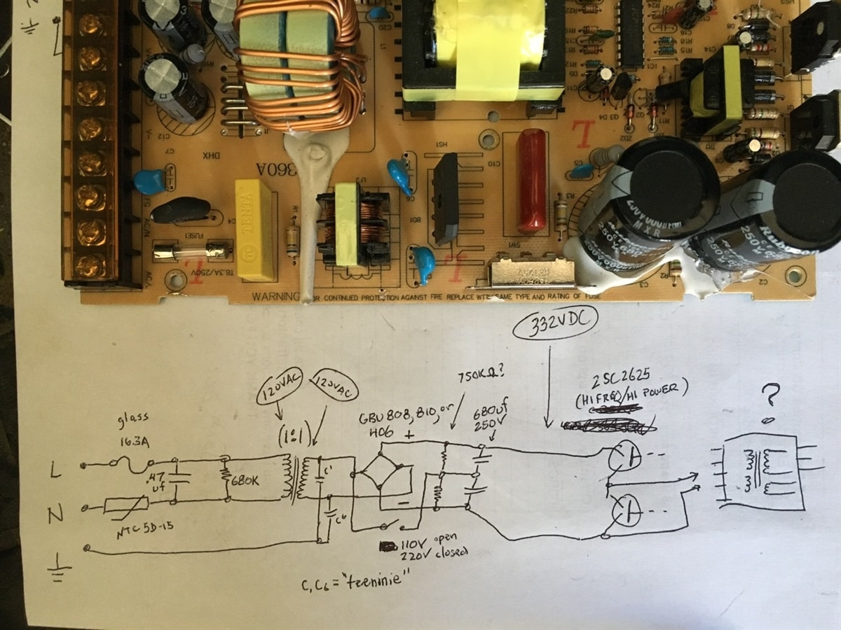
But here’s where it gets goofy: in the process of sampling voltages on the “good” unit, I discovered that DC voltages aft of the bridge rectifier (GBU6J, GBU808, GBU810GBU810, or GBU406GBU406, depending on which board) are 2.75 times that of the AC input. Specifically, I’m getting 330VDC on the back side, with 120VAC going in. I’m including a picture of a “deduced” schematic - up to a point - along with the board itself. Power flows - on the board - from bottom left, anticlockwise around to top left. On the hand-written schematic, C1 and C6 are too small to read, so they got the “teeninie” designation, and probably don’t figure into the puzzle anyway. The pin-out of the semiconductors (2SC2625) after the 680uF electrolytic caps I am not certain of, and so I did not assign a collector/emitter, but based on their description on the spec sheet (“high power, high speed”) I am assuming this is where the 330VDC is chopped up (or modulated) and processed back into AC. The transformer represented by the “?” is the one all the way to the right on the board, nestled behind the big 680uF caps. I can’t begin to guess at the pinouts on that, but there are 3 terminals on one side, and 5 on the other.
so, to reiterate: 120VAC to 330VDC...?
As Professor Quirrell once said “What magic is this?”