element14 Community
element14 Community
    Register Log In
  • Site
  • Search
  • Log In Register
  • About Us
  • Community Hub
    Community Hub
    • What's New on element14
    • Feedback and Support
    • Benefits of Membership
    • Personal Blogs
    • Members Area
    • Achievement Levels
  • Learn
    Learn
    • Ask an Expert
    • eBooks
    • element14 presents
    • Learning Center
    • Tech Spotlight
    • STEM Academy
    • Webinars, Training and Events
    • Learning Groups
  • Technologies
    Technologies
    • 3D Printing
    • FPGA
    • Industrial Automation
    • Internet of Things
    • Power & Energy
    • Sensors
    • Technology Groups
  • Challenges & Projects
    Challenges & Projects
    • Design Challenges
    • element14 presents Projects
    • Project14
    • Arduino Projects
    • Raspberry Pi Projects
    • Project Groups
  • Products
    Products
    • Arduino
    • Avnet Boards Community
    • Dev Tools
    • Manufacturers
    • Multicomp Pro
    • Product Groups
    • Raspberry Pi
    • RoadTests & Reviews
  • Store
    Store
    • Visit Your Store
    • Choose another store...
      • Europe
      •  Austria (German)
      •  Belgium (Dutch, French)
      •  Bulgaria (Bulgarian)
      •  Czech Republic (Czech)
      •  Denmark (Danish)
      •  Estonia (Estonian)
      •  Finland (Finnish)
      •  France (French)
      •  Germany (German)
      •  Hungary (Hungarian)
      •  Ireland
      •  Israel
      •  Italy (Italian)
      •  Latvia (Latvian)
      •  
      •  Lithuania (Lithuanian)
      •  Netherlands (Dutch)
      •  Norway (Norwegian)
      •  Poland (Polish)
      •  Portugal (Portuguese)
      •  Romania (Romanian)
      •  Russia (Russian)
      •  Slovakia (Slovak)
      •  Slovenia (Slovenian)
      •  Spain (Spanish)
      •  Sweden (Swedish)
      •  Switzerland(German, French)
      •  Turkey (Turkish)
      •  United Kingdom
      • Asia Pacific
      •  Australia
      •  China
      •  Hong Kong
      •  India
      •  Korea (Korean)
      •  Malaysia
      •  New Zealand
      •  Philippines
      •  Singapore
      •  Taiwan
      •  Thailand (Thai)
      • Americas
      •  Brazil (Portuguese)
      •  Canada
      •  Mexico (Spanish)
      •  United States
      Can't find the country/region you're looking for? Visit our export site or find a local distributor.
  • Translate
  • Profile
  • Settings
Power & Energy
  • Technologies
  • More
Power & Energy
Forum Linear or Switch Mode Power supply for PWM Driven Stepper Motors?
  • Blog
  • Forum
  • Quiz
  • Documents
  • Polls
  • Events
  • Mentions
  • Sub-Groups
  • Tags
  • More
  • Cancel
  • New
Actions
  • Share
  • More
  • Cancel
Forum Thread Details
  • State Not Answered
  • Replies 16 replies
  • Subscribers 289 subscribers
  • Views 4387 views
  • Users 0 members are here
  • management
  • stepper_motor
  • power_management
  • power_distribution
  • power_supply
  • power
Related

Linear or Switch Mode Power supply for PWM Driven Stepper Motors?

Catwell
Catwell over 15 years ago

I used to use linear power supplies for all my motor control applications. Stepper and servo drivers were all fed with raw linear power. However, recently I have switched to less expensive switching power supplies for the same application. Although I have not seen any performance drop in the motors, I am wondering if I should still stick with a linear supply.


So, to all the motor drive designers out there, is there any real problems with using a switching supply? Would I get smoother motor commutation going linear?


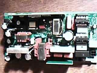
For those who want to know, I am driving 2.1 - 3A per phase stepper motors at 36V. The power supply I am now using supplies switch mode regulated power of 36V at up to 8.8A (350W).


Cabe

  • Sign in to reply
  • Cancel
  • enrico.migchels
    0 enrico.migchels over 15 years ago

    Hi Cabe,


    SMPS performs very nice for motor applications (for any application i would assume) and it will give you the benefit of cost, size and efficiency. As you will use off the shelve products you have to test the power supply on dynamic load response and other important parameters for your specific application. You can not always use the vendor's product specification because your load might interact different than his test load. Most power supplies suppliers use DC current sources to test their products. Load transient of 10A/us might trigger dynamic overcurrent protections. If i may add one comment; if your aim is to build more than one product, test for margin. For example if you need 10A, test for 12A. In this case you will have less to worry about entering mass production.


    Best regards,


    Enrico Migchels

    • Cancel
    • Vote Up 0 Vote Down
    • Sign in to reply
    • Verify Answer
    • Cancel
  • Jorge_Garcia
    0 Jorge_Garcia over 15 years ago

    Hi Cabe,


    You have nothing to worry about in many applications there is no performance cost to be paid by using a Linear Regulator vs. a Switching Regulator. Enrico brings up good points if you are using an off the shelf supply, since in many cases they may not meet transient specifications, not because its a switching regulator but because of shotty workmanship on a device that is inherently more complicated than a Linear Regulator.


    The only application I can think of off the top of my head in which the choice between Linear and switching is important is powering high performance ADCs. Linear regulator simply clamp a high DC voltage to a lower DC voltage, it can be modeled as a resistor that can adjust its resistance depending on the load. In this case the Regulator does not introduce any ripple into the power supply rails, high performance ADCs are sensitive to ripple so it's important to avoid any interference in the form of voltage ripple which raises the ADC noise floor.


    In this application a switching regulator is not so advantageous since it introduces ripple with a frequency equal to the switching frequency of the supply. Switching regulators can operate with frequencies over 1 MHz and the noise they introduce is generally not acceptable. Today switching regulators can be designed to minimize switching ripple and in some cases are acceptable for ADCs but the conventional approach is to use a linear regulator.


    I know I went off topic, but I just wanted to show you when the choice between linear and switching regulators is important. Outside of noise and EMI considerations most applications can take either one.


    Hope this helps.


    Regards,

    Jorge Garcia

    • Cancel
    • Vote Up 0 Vote Down
    • Sign in to reply
    • Verify Answer
    • Cancel
  • enrico.migchels
    0 enrico.migchels over 15 years ago in reply to Jorge_Garcia

    Hi Jorge,


    Let's continue the off-topic discussion for a bit ;-) I think that ripple&noise and EMI is indeed a problem for delicate analog circuits but this can be avoided when the power supply is custom build with a specific application in mind. I know, this is costly. I think it is more acceptable to use a good standard power supply and add a filter stage on the application board for the delicate circuits. Replacing the elcaps on a smps with low ESR types helps greatly. Another critical application is audio. Switching frequences might enter the audio stage. Switch mode and audio is not uncommon anymore. An switch mode audio stage is also interesting and works really nice, but for high end audio a no-go. High end audio has also to do with religion :-)


    Best regards,


    Enrico Migchels

    • Cancel
    • Vote Up 0 Vote Down
    • Sign in to reply
    • Verify Answer
    • Cancel
  • enrico.migchels
    0 enrico.migchels over 15 years ago

    Hi Cabe,


    Your qoute: "The power supply I am now using supplies switch mode regulated power of 36V at up to 8.8A (350W)"


    Similar product 8A/40Vdc and 8A/5Vdc (main converter), 1A/5Vdc (separate standby converter), Triac controlled (PIC16F648A) AC induction motor (900W) .

    Dimensions L: 190mm, W: 90mm H: 50mm


    image

    As this power supply has a DC-power stage of more than 350W, i'm wondering what the dimensions are from your power supply. I build this power supply for a robot vacuum cleaner with AC induction motor (suction) and several Brushless-DC-motors (drive, cordwinder). Maybe i have to add that the AC input is 230Vac and that there is a fan cooling the device.


    Best regards,


    Enrico Migchels

    • Cancel
    • Vote Up 0 Vote Down
    • Sign in to reply
    • Verify Answer
    • Cancel
  • Jorge_Garcia
    0 Jorge_Garcia over 15 years ago in reply to enrico.migchels

    Hi Enrico,


    I definitely agree now and days SMPS can be designed specifically for low ripple on the output stage, I've read several articles on the use of SMPS for powering high precision ADCs.


    I believe your solution is quite workable and in fact is often implemented.


    I would like to mention a minor point on the Audio App. I'm not specialized in Audio but I believe that in Analog amplifiers high frequency switching noise would not be that large an issue. The human ear can detect signals from 20hz-20khz approximately, any noise with a frequency outside of this range would be undetected by a listener, this is handy for the design of simple amplifiers.


    Class D(or C I don't recall) amplifiers I believe make use of this idea. In their simplest for the the audio signal is the input to a PWM circuit whose output is then filtered to to retrieve an amplified version of the original signal. Any high frequency residuals are ignored due to the human ear's natural cutoff.


    A digital audio system would be adversely affected due to aliasing from sampling(Nyquist). I'm splitting hairs I know, you are completely correct in your comment, but I just felt like ranting a little;-).


    Regards,

    Jorge Garcia

    • Cancel
    • Vote Up 0 Vote Down
    • Sign in to reply
    • Verify Answer
    • Cancel
  • Former Member
    0 Former Member over 11 years ago

    Hello guys, this is my first post to this forum. I realize is a very old post but I will write it anyway.


    I think you might have problems driving motors with SMPS if you have energy coming back from the motor to the power supply. Specialy if the SMPS its too cheap.


    I am working on a power supply that will drive a few servomotors. I came accross the link below on the driver manufacturer website.


    http://www.elmomc.com/applications/Power-Supply-for-Servo-Applications.htm#11


    I believe if you don´t expect too much regeneration, adding some extra capacitance should mitigate the problem. But if you expect more, then a shunt resistor it´s probably a better call.


    As for my application, I still don´t know what to do. I don´t expect too much regeneration (almost none actually) but I need it to last for several years. So even a little damage to the power supply on the long run might be bad.


    But this is my first impression on the subject. I will probably change my mind a couple times before final solution. image

    • Cancel
    • Vote Up 0 Vote Down
    • Sign in to reply
    • Verify Answer
    • Cancel
  • D_Hersey
    0 D_Hersey over 11 years ago

    The way to go with a stepper motor is to use an un-regulated DC supply, then employ a chopping CCS on the motor coils.  Now you have the virtue of switching regulation, but retain the large filter cap to dump your spikes into.


    CCS drive has worked very well for me in using stepping motors.  Much less likely to experience output resonance, better torque.

    • Cancel
    • Vote Up 0 Vote Down
    • Sign in to reply
    • Verify Answer
    • Cancel
  • Former Member
    0 Former Member over 11 years ago in reply to D_Hersey

    Don, what is a chopping CCS? Is that a type of driver? The motor I have here is a servomotor, does the same approach applies?

    • Cancel
    • Vote Up 0 Vote Down
    • Sign in to reply
    • Verify Answer
    • Cancel
  • D_Hersey
    0 D_Hersey over 11 years ago

    Yes, it can work for servo-motors as well.  There are a few ways to achieve this result.  I am a stinker to use the abbreviation 'CCS' because it literally stands for 'constant current source,' when I mean 'constant current sink.'  In Si, electrons are a little lighter and faster than holes.  So if a circuit could use either an N-type or a P-type power switch, we choose the N-type.


    The principle is simple.  Nature provides us with potential ('voltage') sources more often than current sources.  Energy stored in a coil is LII/2.  That energy, in the case of our motor, goes mostly into magnetizing the core.  We would like to energize our motor with a constant current  source, since then our magnetic flux would be established immediately and our motor could then go really, really fast.  Current sources, alas, don't really exist, we have to simulate them.  Here, momentarily, our CCS would have to be able to source nearly infinite potential!  Nature, of course does not supply us with either an ideal current source nor an ideal voltage source.  This shows us, once again, the good grace of the almighty:  If V=IR and Power = IV, crowbar-ing a voltage source or leaving a current source open would destroy the universe, obviating whatever purpose our project entailed.  Batteries are ideal voltage sources coupled with intrinsic, series (Thevenin) resistors.  Current sources would have intrinsic shunt (Norton) resistors, keeping our world intact.  It is equivalent, and maybe a bit more ingenuous to state that current-sources have a 'voltage-compliance-limit.'


    What happens in real life is that a super-voltage is temporarily applied to our coil when we want to start it up or change its direction.  Back emf provided by our load temporarily makes it seem to be a more resistive load than it really is, momentarily, until the core saturates.  Once it does, we often want to reduce our current, in the case of a stepper, down to an amount that represents 'holding torque,' rather than an attempt to further turn the rotor.


    Current is sensed, somehow, the simplest method being a current-sensing resistor.  This is used as the sensor in a negative-feedback loop that either modulates the conductance of, or chops the power switch, simulating a current source.


    Physically, now our (stepping motor) has an extra spurt of power when beginning to transition.  Since I have reached my majority, I seem to fart when I de-couch.  The kids around here refer to this as turbo-assist.  I am not always that good with analogy.


    Sometimes, we need to use Ohm's law to infer coil current from published potentials and coil resistances.  This is usually with small motors.

    • Cancel
    • Vote Up 0 Vote Down
    • Sign in to reply
    • Verify Answer
    • Cancel
  • D_Hersey
    0 D_Hersey over 11 years ago

    Linear CCS in concept:

    image

    • Cancel
    • Vote Up 0 Vote Down
    • Sign in to reply
    • Verify Answer
    • Cancel
>
element14 Community

element14 is the first online community specifically for engineers. Connect with your peers and get expert answers to your questions.

  • Members
  • Learn
  • Technologies
  • Challenges & Projects
  • Products
  • Store
  • About Us
  • Feedback & Support
  • FAQs
  • Terms of Use
  • Privacy Policy
  • Legal and Copyright Notices
  • Sitemap
  • Cookies

An Avnet Company © 2025 Premier Farnell Limited. All Rights Reserved.

Premier Farnell Ltd, registered in England and Wales (no 00876412), registered office: Farnell House, Forge Lane, Leeds LS12 2NE.

ICP 备案号 10220084.

Follow element14

  • X
  • Facebook
  • linkedin
  • YouTube