element14 Community
element14 Community
    Register Log In
  • Site
  • Search
  • Log In Register
  • About Us
  • Community Hub
    Community Hub
    • What's New on element14
    • Feedback and Support
    • Benefits of Membership
    • Personal Blogs
    • Members Area
    • Achievement Levels
  • Learn
    Learn
    • Ask an Expert
    • eBooks
    • element14 presents
    • Learning Center
    • Tech Spotlight
    • STEM Academy
    • Webinars, Training and Events
    • Learning Groups
  • Technologies
    Technologies
    • 3D Printing
    • FPGA
    • Industrial Automation
    • Internet of Things
    • Power & Energy
    • Sensors
    • Technology Groups
  • Challenges & Projects
    Challenges & Projects
    • Design Challenges
    • element14 presents Projects
    • Project14
    • Arduino Projects
    • Raspberry Pi Projects
    • Project Groups
  • Products
    Products
    • Arduino
    • Avnet Boards Community
    • Dev Tools
    • Manufacturers
    • Multicomp Pro
    • Product Groups
    • Raspberry Pi
    • RoadTests & Reviews
  • Store
    Store
    • Visit Your Store
    • Choose another store...
      • Europe
      •  Austria (German)
      •  Belgium (Dutch, French)
      •  Bulgaria (Bulgarian)
      •  Czech Republic (Czech)
      •  Denmark (Danish)
      •  Estonia (Estonian)
      •  Finland (Finnish)
      •  France (French)
      •  Germany (German)
      •  Hungary (Hungarian)
      •  Ireland
      •  Israel
      •  Italy (Italian)
      •  Latvia (Latvian)
      •  
      •  Lithuania (Lithuanian)
      •  Netherlands (Dutch)
      •  Norway (Norwegian)
      •  Poland (Polish)
      •  Portugal (Portuguese)
      •  Romania (Romanian)
      •  Russia (Russian)
      •  Slovakia (Slovak)
      •  Slovenia (Slovenian)
      •  Spain (Spanish)
      •  Sweden (Swedish)
      •  Switzerland(German, French)
      •  Turkey (Turkish)
      •  United Kingdom
      • Asia Pacific
      •  Australia
      •  China
      •  Hong Kong
      •  India
      •  Korea (Korean)
      •  Malaysia
      •  New Zealand
      •  Philippines
      •  Singapore
      •  Taiwan
      •  Thailand (Thai)
      • Americas
      •  Brazil (Portuguese)
      •  Canada
      •  Mexico (Spanish)
      •  United States
      Can't find the country/region you're looking for? Visit our export site or find a local distributor.
  • Translate
  • Profile
  • Settings
Power & Energy
  • Technologies
  • More
Power & Energy
Forum Charging two GP Ion-Li Battery packs with only one IC?
  • Blog
  • Forum
  • Quiz
  • Documents
  • Polls
  • Events
  • Mentions
  • Sub-Groups
  • Tags
  • More
  • Cancel
  • New
Actions
  • Share
  • More
  • Cancel
Forum Thread Details
  • State Verified Answer
  • Replies 34 replies
  • Answers 4 answers
  • Subscribers 287 subscribers
  • Views 2896 views
  • Users 0 members are here
  • pack
  • li-ion
  • battery
  • charger
Related

Charging two GP Ion-Li Battery packs with only one IC?

Former Member
Former Member over 13 years ago

Hello,


I have this two Li-Ion Battery packs from GP Batteries:


7.4V

http://es.farnell.com/jsp/search/productdetail.jsp?SKU=1848661


11.1V

http://es.farnell.com/jsp/search/productdetail.jsp?SKU=1848662


I have put them in series -> 18.5V

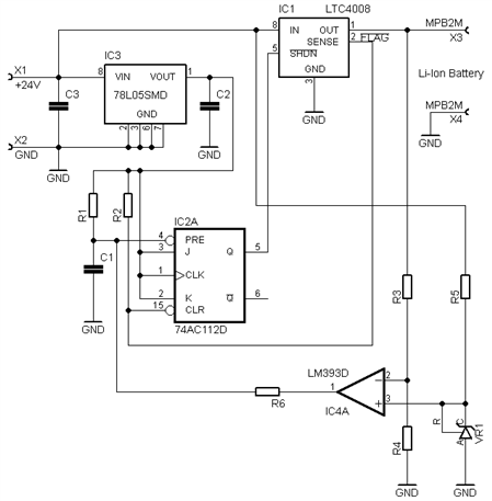
I want them to charge with for example LTC4008EGN#PBFLTC4008EGN#PBF from Linear Tech.

http://es.farnell.com/linear-technology/ltc4008egn-pbf/cargador-de-baterias-smd-ssop20/dp/1273983?Ntt=ltc4008


Question is, what happens if one of the packs is medium-charged and the other completely discharged? I understand that in a certain moment one of the packs will be charged, but what happens with the other pack?

Will continue charging? Will the charged pack be damaged? Or simply one of the packs will remain without being charged?


Is it imperative in this scenario to use one charger for each pack??


Thanks for any tip.


Regards,


Cristian.


  • Sign in to reply
  • Cancel
Parents
  • RWM
    0 RWM over 13 years ago

    Hi Cristian,


    as battery packs are equipped with protection circuits (over-charge over-discharge etc. - see datasheet page 6), they should be charged separately. If two packs will be connected in series and will be in different state of charge, when charging protection circuit in one pack will detect overvoltage, it will disconnect this pack, so charging of second pack will be stopped.


    If there will be other battery pack without protection circuits, it would be possible to connect packs in series and charge from one charger but blancing circuit should be used. It protects cells from overcharging.

    • Cancel
    • Vote Up 0 Vote Down
    • Sign in to reply
    • Verify Answer
    • Reject Answer
    • Cancel
  • Former Member
    0 Former Member over 13 years ago in reply to RWM

    Hi,


    I have chosen two IC Chargers for each of the two Li-Ion packs. Now when I´m going to design the circuit I realize that if this two packs are connected in series, the GND of the 24V that powers the two IC chargers must be different on each other.


    It´s an automatic charger so I can´t disconnect the packs. So, do I need two source powers? I fear that it will be the only possibility... Anyone has pass through this?


    Thanks in advance


    Regards,


    Cristian

    • Cancel
    • Vote Up 0 Vote Down
    • Sign in to reply
    • Verify Answer
    • Cancel
  • Former Member
    0 Former Member over 12 years ago in reply to Former Member

    CD74ACT112M could do it

    http://es.farnell.com/texas-instruments/cd74act112m/logic-dual-jk-neg-edg-trg-ff-16soic/dp/1752830


    connecting !FLAG to the clock, in the falling edge will transfer J K inputs to the outputs... just with a pull-up in the output will be set the initial state, then when clock falls J and K goes to the output, making it low shutting down the ltc..

    later with !PRE or !CLR it can reset the states of the output.


    I think that would work...

    • Cancel
    • Vote Up 0 Vote Down
    • Sign in to reply
    • Verify Answer
    • Cancel
  • RWM
    0 RWM over 12 years ago in reply to Former Member

    Hi,


    you can use only !CLR and !PRE inputs - !CLR to shutdown charger and !PRE to start next charging cycle. Of course power-up conditions must be set (e.g. small capacitor to ground and resistor to 74ACT112 Vcc on !PRE). As !FLAG is open drain output, you must also add pull-up resistor to this output. Circuit detecting battery voltage below discharge level (e.g. comparator with active low signal) should be connected to !PRE.


    Flip-flop outputs are push-pull, pull-up will not set a state. State should be set on inputs (!PRE or !CLR).


    You can also use popular AHC74 flip-flop (wider supply voltage range 2-5.5V)

    http://es.farnell.com/texas-instruments/sn74ahc74n/logic-dual-pos-edg-trg-d-f-f-14dip/dp/1749933


    or two gates to form RS flip-flop.

    • Cancel
    • Vote Up 0 Vote Down
    • Sign in to reply
    • Verify Answer
    • Cancel
  • Former Member
    0 Former Member over 12 years ago in reply to RWM

    Interesting,


    Assuming only one cycle charge I see this other configuration (the same as yours but changing PRE! for shutdown instead of !CLR) I think is the same:


    Initial conditions:

    !PRE = HIGH with a pull-up to vcc (connected to !FLAG indicator)

    !CLR = LOW (directly to GND) or capacitor to GND..


    (datasheet of flipflop): http://www.ti.com/lit/ds/symlink/cd74act112.pdf


    so that makes Q=Low (connected to !SHDN)  &  !Q=High


    If I take Q as output and connect it to !SHDN (LTC4008) -> it will never turn on, the charger will remain OFF

    I can´t take !Q as output because it will not change when !PRE goes low.


    So I´m thinking about an inverter in Q output... so... Q will be High (instead of Low) -> that makes LTC4008 to start charging, because ACP/!SHDN is high


    When C/10 indicator (!FLAG) goes low, we have !PRE and !CLR = low, that makes Q=high  &  !Q=high  , but because of the inverter in Q... Q=low... LTC4008 is shutted down, good!

    But then... !FLAG will return to High that means that !PRE=High and !CLR=low again... so... it will be turned on again... and infinite loop cames again.


    I think the only way to achieve this is use CLK input of the Flip Flop with the falling edge detector, because !FLAG is going to make a pulse, because when shutting down, !FLAG will return to High...

    But then... !PRE and !CLR must be first configured and later make both of them HIGH, then with !FLAG connected to Clk there should be no problem...


    Problem is how to set initial state and the make both high...

    I cannot see it working in another way... image


    Thanks for the push-pull warning!


    • Cancel
    • Vote Up 0 Vote Down
    • Sign in to reply
    • Verify Answer
    • Cancel
  • Former Member
    0 Former Member over 12 years ago in reply to Former Member

    Well, after trying to discover a way on how to use !FLAG and !SHDN inputs of LTC4008 with a flip-flop, I found that is not possible without a more complex ...

    I think that the use of a microcontroller is needed for manage it.


    But, just started to think on another way to achieve this and voila! Vprog appeared.

    "The voltage at this pin provides a linear indication of charging current."

    ... image ...


    So, if Vprog reaches a low voltage value, with a comparator I can shutdown the charger. Once is turned off... it remains off because Vprog=GND


    What I´m afraid again, is the starting point, when plugging, Vprog need to rise fast enough to keep the charger ON.

    A pull-up in the output comparator (connected to !SHDN) maybe helps.

    I´m going to try this in these days and post the results.

    • Cancel
    • Vote Up 0 Vote Down
    • Sign in to reply
    • Verify Answer
    • Cancel
  • RWM
    0 RWM over 12 years ago in reply to Former Member

    !CLR and !PRE inputs are not intended to be driven low for long time. They should be used to set/reset output of flip-flop using short pulse. State when both !CLR and !PRE are driven low should be avoided because outputs states are unpredictable when both inputs will go high simulataneously.


    If !PRE will be connected to reset circuit (resistor to Vcc and capacitor to GND) and !CLR to !FLAG, flip-flop output Q will be set to high when power goes on and to low when !FLAG will go low. Q connected with !SHDN will shutdown charger circuit, so !FLAG will be unactive and charging will be terminated. If a comparator with active low signal when battery voltage fall below 3.0V/cell will be connected to !PRE, charging cycle will start when battery will be discharged.


    Output of comparator is determined by input voltages, pull-up is needed when comparator has open collector output (like LM393, LM339) but will not set output state.

    • Cancel
    • Vote Up 0 Vote Down
    • Sign in to reply
    • Verify Answer
    • Cancel
  • Former Member
    0 Former Member over 12 years ago in reply to RWM

    Hi, thanks for the answer,


    If charger is ON, !FLAG will be HIGH, that means !CLR will be HIGH.


    But, !PRE needs to be LOW for making Q=HIGH... and when !FLAG goes down, !PRE needs to change for being HIGH.

    What I don´t understand is the "reset circuit" conected to !PRE... how is supposed to work that "reset circuit"?


    The other problem I see is that !FLAG, once is LOW, it will return to HIGH, because the charger is OFF, and it will be kept open (not high neither low)... and we have a pull-up connected to !FLAG...


    Regards,


    Cristian.

    • Cancel
    • Vote Up 0 Vote Down
    • Sign in to reply
    • Verify Answer
    • Cancel
  • RWM
    0 RWM over 12 years ago in reply to Former Member

    Hi,


    "reset circuit" means circuit which sets right level on right input on start-up. On schematic below it is R1 C1. It sets low level for short time on !PRE input, so Q is set to high level and charger can work. After short time capacitor C1 will charge and level on !PRE input will be high. When !FLAG will go low, it will set !CLR low and Q low, so !SHDN will go low and charger will be switched off. Then !FLAG will be open drain, but due to R2 signal level on !CLR will be high.


    image

    For automatic recharging comparator IC4 can be used. When batey voltage falls below certain level VR1*(R3+R4)/R4, its output will go low and !PRE will go low and finally Q will go high and charger should start. Battery voltage will increase, so IC4 output will go high.


    Best regards,


    Ryszard

    • Cancel
    • Vote Up 0 Vote Down
    • Sign in to reply
    • Verify Answer
    • Cancel
  • Former Member
    0 Former Member over 12 years ago in reply to RWM

    Marvellous!


    I´ve been enlightened with this image


    with a bit of simulation, timings will be achieved without problem.


    Thank you very much for the help and very elegant solution...As always, It has been a pleasure talk

    For sure, this post will help more people, and I hope so.


    All the best from Madrid!

    • Cancel
    • Vote Up 0 Vote Down
    • Sign in to reply
    • Verify Answer
    • Cancel
  • RWM
    0 RWM over 12 years ago in reply to Former Member

    Thanks!


    I hope this will work ;-)


    R1C1 timing can be about 100 ms or so (voltages across circuit should stabilize)


    Please share your findings if you will build a prototype.


    Best regards,


    Ryszard

    • Cancel
    • Vote Up 0 Vote Down
    • Sign in to reply
    • Verify Answer
    • Cancel
  • Former Member
    0 Former Member over 12 years ago in reply to RWM

    thanks,


    I have put all the mosfets results in this thread:

    http://www.element14.com/community/message/75029#75029/l/re-mosfet-recomendation-for-ltc4008-li-ion-charger-5-cells-pack


    The thermistor network is perfect. At 45ºC the LTC4008 stops the charging operation... I have not tested yet 0ºC but I think it will be perfect...


    this is the circuit for the thermistor I have used:


    image


    Thermistor Model:

    Vishay NTCLE203E3103FB0


    Please feel free to ask me about any section of the circuit.


    When I build the flip-flop I will post the results also.


    Best Regards,


    Cristian.

    • Cancel
    • Vote Up 0 Vote Down
    • Sign in to reply
    • Verify Answer
    • Cancel
Reply
  • Former Member
    0 Former Member over 12 years ago in reply to RWM

    thanks,


    I have put all the mosfets results in this thread:

    http://www.element14.com/community/message/75029#75029/l/re-mosfet-recomendation-for-ltc4008-li-ion-charger-5-cells-pack


    The thermistor network is perfect. At 45ºC the LTC4008 stops the charging operation... I have not tested yet 0ºC but I think it will be perfect...


    this is the circuit for the thermistor I have used:


    image


    Thermistor Model:

    Vishay NTCLE203E3103FB0


    Please feel free to ask me about any section of the circuit.


    When I build the flip-flop I will post the results also.


    Best Regards,


    Cristian.

    • Cancel
    • Vote Up 0 Vote Down
    • Sign in to reply
    • Verify Answer
    • Cancel
Children
No Data
element14 Community

element14 is the first online community specifically for engineers. Connect with your peers and get expert answers to your questions.

  • Members
  • Learn
  • Technologies
  • Challenges & Projects
  • Products
  • Store
  • About Us
  • Feedback & Support
  • FAQs
  • Terms of Use
  • Privacy Policy
  • Legal and Copyright Notices
  • Sitemap
  • Cookies

An Avnet Company © 2025 Premier Farnell Limited. All Rights Reserved.

Premier Farnell Ltd, registered in England and Wales (no 00876412), registered office: Farnell House, Forge Lane, Leeds LS12 2NE.

ICP 备案号 10220084.

Follow element14

  • X
  • Facebook
  • linkedin
  • YouTube