element14 Community
element14 Community
    Register Log In
  • Site
  • Search
  • Log In Register
  • Community Hub
    Community Hub
    • What's New on element14
    • Feedback and Support
    • Benefits of Membership
    • Personal Blogs
    • Members Area
    • Achievement Levels
  • Learn
    Learn
    • Ask an Expert
    • eBooks
    • element14 presents
    • Learning Center
    • Tech Spotlight
    • STEM Academy
    • Webinars, Training and Events
    • Learning Groups
  • Technologies
    Technologies
    • 3D Printing
    • FPGA
    • Industrial Automation
    • Internet of Things
    • Power & Energy
    • Sensors
    • Technology Groups
  • Challenges & Projects
    Challenges & Projects
    • Design Challenges
    • element14 presents Projects
    • Project14
    • Arduino Projects
    • Raspberry Pi Projects
    • Project Groups
  • Products
    Products
    • Arduino
    • Avnet Boards Community
    • Dev Tools
    • Manufacturers
    • Multicomp Pro
    • Product Groups
    • Raspberry Pi
    • RoadTests & Reviews
  • Store
    Store
    • Visit Your Store
    • Choose another store...
      • Europe
      •  Austria (German)
      •  Belgium (Dutch, French)
      •  Bulgaria (Bulgarian)
      •  Czech Republic (Czech)
      •  Denmark (Danish)
      •  Estonia (Estonian)
      •  Finland (Finnish)
      •  France (French)
      •  Germany (German)
      •  Hungary (Hungarian)
      •  Ireland
      •  Israel
      •  Italy (Italian)
      •  Latvia (Latvian)
      •  
      •  Lithuania (Lithuanian)
      •  Netherlands (Dutch)
      •  Norway (Norwegian)
      •  Poland (Polish)
      •  Portugal (Portuguese)
      •  Romania (Romanian)
      •  Russia (Russian)
      •  Slovakia (Slovak)
      •  Slovenia (Slovenian)
      •  Spain (Spanish)
      •  Sweden (Swedish)
      •  Switzerland(German, French)
      •  Turkey (Turkish)
      •  United Kingdom
      • Asia Pacific
      •  Australia
      •  China
      •  Hong Kong
      •  India
      •  Korea (Korean)
      •  Malaysia
      •  New Zealand
      •  Philippines
      •  Singapore
      •  Taiwan
      •  Thailand (Thai)
      • Americas
      •  Brazil (Portuguese)
      •  Canada
      •  Mexico (Spanish)
      •  United States
      Can't find the country/region you're looking for? Visit our export site or find a local distributor.
  • Translate
  • Profile
  • Settings
Power & Energy
  • Technologies
  • More
Power & Energy
Forum Single Phase to three signal generator.
  • Blog
  • Forum
  • Quiz
  • Documents
  • Polls
  • Events
  • Mentions
  • Sub-Groups
  • Tags
  • More
  • Cancel
  • New
Actions
  • Share
  • More
  • Cancel
Forum Thread Details
  • State Verified Answer
  • Replies 14 replies
  • Subscribers 285 subscribers
  • Views 2929 views
  • Users 0 members are here
  • power supply
  • circuit
  • power_supply
  • power
  • power.power
Related

Single Phase to three signal generator.

Jere9522
Jere9522 over 2 years ago

Hello everyone,
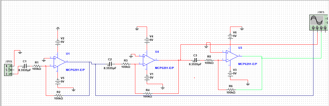
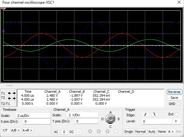
I am designing a low voltage power supply that will run single phase to three phase circuit and will be using ultrosonic frequency as its signal input. The current circuit design uses three operational amplifiers that has a 60 degress phase shift. I am encountering a problem with regards to the output amplitude of the three phase signals. It seems to have a decrease in the amplitude. I also used RC oscillator circuit in front of the op-amp to have a precise phase shift. I am asking for any suggestions or how to deal with this problem? Also, are there any concept that I can study to approach this problem? I am also thinking to apply DSP filtering to elimate the noise in the output. Thank you in advance.

  • Sign in to reply
  • Cancel

Top Replies

  • shabaz
    shabaz over 2 years ago +2 verified
    I'm not entirely sure what you're looking for, especially the ultrasonic bit! A diagram would definitely help. For the 3-phase generation portion, in theory that's quite easy using any microcontroller…
  • genebren
    genebren over 2 years ago +2 verified
    It would appear from your schematic, that because the output of the first stage, feeds the input of the second stage, and the output of the second stage feeds the input for the third, the amplitude changes…
  • jc2048
    jc2048 over 2 years ago in reply to Jere9522 +2
    Don't try it as you've drawn it. The maximum supply for a MCP6291 is 6V, 10V will blow it up.
  • rscasny
    0 rscasny over 2 years ago

    Do you have a visual, like a block diagram? That might help people better see what you are doing.

    • Cancel
    • Vote Up +1 Vote Down
    • Sign in to reply
    • Verify Answer
    • Cancel
  • shabaz
    +1 shabaz over 2 years ago

    I'm not entirely sure what you're looking for, especially the ultrasonic bit!

    A diagram would definitely help.

    For the 3-phase generation portion, in theory that's quite easy using any microcontroller with PWM, and a simple filter to construct the waveforms from that:

    /technologies/power-management/b/blog/posts/building-a-three-phase-mains-power-system-simulator

    However you may have different requirements so it needs more info. (the microcontroller approach just mentioned only works at low frequencies, not ultrasonic).

    • Cancel
    • Vote Up +2 Vote Down
    • Sign in to reply
    • Reject Answer
    • Cancel
  • Jere9522
    0 Jere9522 over 2 years ago in reply to rscasny

    image

    image

    Here is the circuit and the output. The input in the signal gen is 110kHz and 4Vp.

    • Cancel
    • Vote Up 0 Vote Down
    • Sign in to reply
    • Verify Answer
    • Cancel
  • Jere9522
    0 Jere9522 over 2 years ago in reply to shabaz

    image

    image

    Here is my initial circuit, the output signal will be use as a frequency output for a transducer

    • Cancel
    • Vote Up 0 Vote Down
    • Sign in to reply
    • Verify Answer
    • Cancel
  • genebren
    +1 genebren over 2 years ago

    It would appear from your schematic, that because the output of the first stage, feeds the input of the second stage, and the output of the second stage feeds the input for the third, the amplitude changes are being caused by a gain less that one in each stage.  You could test this by increasing the resistance for R2, R4 and R6 to increase the gains.  The gains appear to be about 0.5 right now, so you might want to double the resistance.  Good luck

    • Cancel
    • Vote Up +2 Vote Down
    • Sign in to reply
    • Reject Answer
    • Cancel
  • Jere9522
    0 Jere9522 over 2 years ago in reply to genebren

    Thanks! I will try this approach. 

    • Cancel
    • Vote Up 0 Vote Down
    • Sign in to reply
    • Verify Answer
    • Cancel
  • Jan Cumps
    0 Jan Cumps over 2 years ago in reply to genebren

    I think that the amplitude loss is caused by the capacitor. The OpAmps seem to have unity gain.

    • Cancel
    • Vote Up +1 Vote Down
    • Sign in to reply
    • Verify Answer
    • Cancel
  • jc2048
    0 jc2048 over 2 years ago in reply to Jere9522

    Don't try it as you've drawn it. The maximum supply for a MCP6291 is 6V, 10V will blow it up.

    • Cancel
    • Vote Up +2 Vote Down
    • Sign in to reply
    • Verify Answer
    • Cancel
  • genebren
    0 genebren over 2 years ago in reply to Jan Cumps

    At 110KHz, the 8.353pF capacitor has an impedance of 173KΩ, which is in series with the 100KΩ, so yes the capacitance is effecting the gain.  One way to change the gain is to increase the feedback resistance.

    • Cancel
    • Vote Up +2 Vote Down
    • Sign in to reply
    • Verify Answer
    • Cancel
  • phoenixcomm
    0 phoenixcomm over 2 years ago

    First, let me quote you. 

    "I am designing a low-voltage power supply that will run single-phase to three-phase circuit and will be using ultrasonic frequency as its signal input. The current circuit design uses three operational amplifiers that has a 60 degrees phase shift."

    To convert single-phase to three-phase should be at 120 degrees apart, Not 60 degrees as 60+60+60 = 180 degrees not 360 degrees. Also, your scope trace clearly shows two signals not three. I work at 400Hz and I use three audio amps to provide isolation. And besides my target voltage is 48 vac which I step up to 11 5vac to get a clean signal you will need to clean up the source I assume ( your input is a PWM output from sort of a processor )  you can clean it up with a RC network.  this would be phase A, then you need to delay it 120 degrees for phase B and one more time to get the phase C. 

    • Cancel
    • Vote Up +1 Vote Down
    • Sign in to reply
    • Verify Answer
    • Cancel
>
element14 Community

element14 is the first online community specifically for engineers. Connect with your peers and get expert answers to your questions.

  • Members
  • Learn
  • Technologies
  • Challenges & Projects
  • Products
  • Store
  • About Us
  • Feedback & Support
  • FAQs
  • Terms of Use
  • Privacy Policy
  • Legal and Copyright Notices
  • Sitemap
  • Cookies

An Avnet Company © 2025 Premier Farnell Limited. All Rights Reserved.

Premier Farnell Ltd, registered in England and Wales (no 00876412), registered office: Farnell House, Forge Lane, Leeds LS12 2NE.

ICP 备案号 10220084.

Follow element14

  • X
  • Facebook
  • linkedin
  • YouTube