element14 Community
element14 Community
    Register Log In
  • Site
  • Search
  • Log In Register
  • About Us
  • Community Hub
    Community Hub
    • What's New on element14
    • Feedback and Support
    • Benefits of Membership
    • Personal Blogs
    • Members Area
    • Achievement Levels
  • Learn
    Learn
    • Ask an Expert
    • eBooks
    • element14 presents
    • Learning Center
    • Tech Spotlight
    • STEM Academy
    • Webinars, Training and Events
    • Learning Groups
  • Technologies
    Technologies
    • 3D Printing
    • FPGA
    • Industrial Automation
    • Internet of Things
    • Power & Energy
    • Sensors
    • Technology Groups
  • Challenges & Projects
    Challenges & Projects
    • Design Challenges
    • element14 presents Projects
    • Project14
    • Arduino Projects
    • Raspberry Pi Projects
    • Project Groups
  • Products
    Products
    • Arduino
    • Avnet Boards Community
    • Dev Tools
    • Manufacturers
    • Multicomp Pro
    • Product Groups
    • Raspberry Pi
    • RoadTests & Reviews
  • Store
    Store
    • Visit Your Store
    • Choose another store...
      • Europe
      •  Austria (German)
      •  Belgium (Dutch, French)
      •  Bulgaria (Bulgarian)
      •  Czech Republic (Czech)
      •  Denmark (Danish)
      •  Estonia (Estonian)
      •  Finland (Finnish)
      •  France (French)
      •  Germany (German)
      •  Hungary (Hungarian)
      •  Ireland
      •  Israel
      •  Italy (Italian)
      •  Latvia (Latvian)
      •  
      •  Lithuania (Lithuanian)
      •  Netherlands (Dutch)
      •  Norway (Norwegian)
      •  Poland (Polish)
      •  Portugal (Portuguese)
      •  Romania (Romanian)
      •  Russia (Russian)
      •  Slovakia (Slovak)
      •  Slovenia (Slovenian)
      •  Spain (Spanish)
      •  Sweden (Swedish)
      •  Switzerland(German, French)
      •  Turkey (Turkish)
      •  United Kingdom
      • Asia Pacific
      •  Australia
      •  China
      •  Hong Kong
      •  India
      •  Korea (Korean)
      •  Malaysia
      •  New Zealand
      •  Philippines
      •  Singapore
      •  Taiwan
      •  Thailand (Thai)
      • Americas
      •  Brazil (Portuguese)
      •  Canada
      •  Mexico (Spanish)
      •  United States
      Can't find the country/region you're looking for? Visit our export site or find a local distributor.
  • Translate
  • Profile
  • Settings
Power & Energy
  • Technologies
  • More
Power & Energy
Forum Oscillating signal splitter into 3 output
  • Blog
  • Forum
  • Quiz
  • Documents
  • Polls
  • Events
  • Mentions
  • Sub-Groups
  • Tags
  • More
  • Cancel
  • New
Actions
  • Share
  • More
  • Cancel
Forum Thread Details
  • State Not Answered
  • Replies 4 replies
  • Subscribers 285 subscribers
  • Views 1627 views
  • Users 0 members are here
Related

Oscillating signal splitter into 3 output

Jere9522
Jere9522 over 2 years ago

Hello everyone,

I am a creating a driver circuit for PZT atomizer transducer with a resonance frequency of 110kHz. The current design to split the signal in to three is by means of 3 cascaded op-amp. Also I am thinking to apply Phase locked loop in every output for the transducer to work at its resonance in the long run. 
Are there other ways to split oscillated signal into three? What techniques and concept can I apply with this? Thank you in advance for the answers, much appreciated.

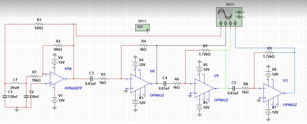
This is the Oscillator circuit with cascaded amplifier as three signal splitter

image

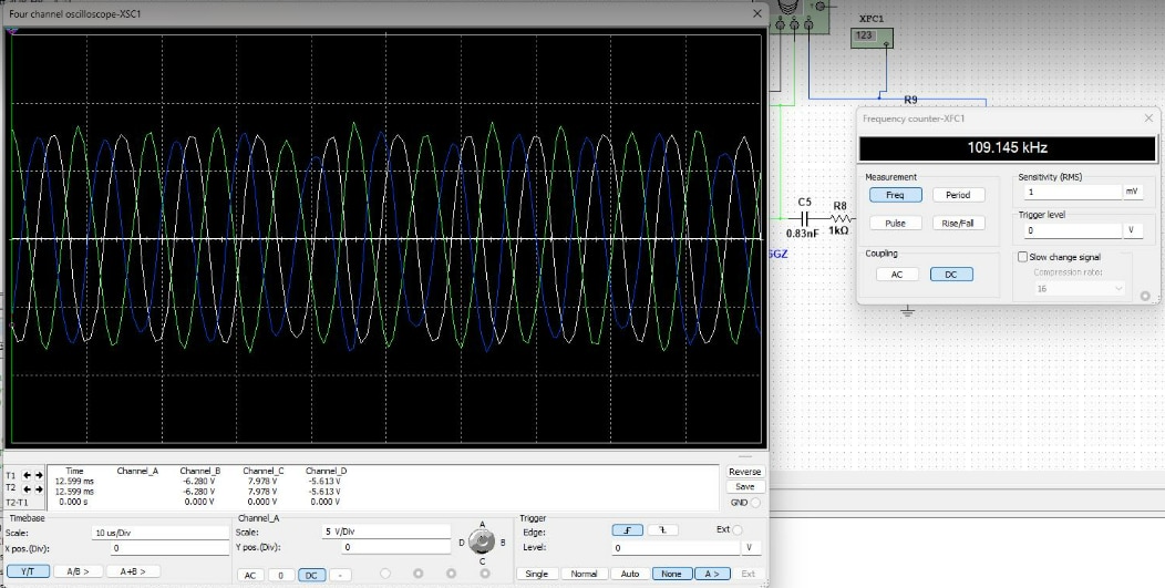
Here is the output waveform, with 60 phase shift each output.

image

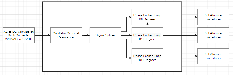
Here is the block diagram, which will be the overall system of the driver circuit.

image

  • Sign in to reply
  • Cancel

Top Replies

  • dougw
    dougw over 2 years ago +2
    If the atomizers don't all have exactly the same resonant frequency, it doesn't seem possible to lock on the resonant frequencies and still maintain a 60 degree phase shift. Why do you need to have a…
  • Jan Cumps
    Jan Cumps over 2 years ago in reply to shabaz +2
    I was thinking about this design, self oscillating at a frequency of choice (110 kHz) with the 60° 120° and 180° available: Ignore the R and C values - I just entered them to get LTSpice running…
  • dougw
    0 dougw over 2 years ago

    If the atomizers don't all have exactly the same resonant frequency, it doesn't seem possible to lock on the resonant frequencies and still maintain a 60 degree phase shift.

    Why do you need to have a fixed phase difference?

    I think it might be possible to design the phase lock circuits to have 60 degree differences without the splitter, but they couldn't lock to different resonant frequencies at the same time. 

    • Cancel
    • Vote Up +2 Vote Down
    • Sign in to reply
    • Verify Answer
    • Cancel
  • shabaz
    0 shabaz over 2 years ago

    Hi,

    It's good you have a diagram, not many people make that effort, but it's bad it doesn't make sense (to me at least). From left to right:
    Regarding 'oscillator circuit at resonance', you have a resonant circuit as part of your oscillator, so of course it will resonate. It's like a tautology.

    Next, what you're calling a 'signal splitter' isn't a splitter. It's some sort of delay circuit with op-amp buffers.
    Finally, what's the point of the PLL, where is your VCO, it's absent, and what would that achieve in any case?

    Trying to guess the intent, it seems you might wish to adjust each output frequency slightly and thought the third stage in your diagram would do that? As Doug mentions, how would you maintain the phase difference if each frequency is different? I think you need to reconsider that.

    Personally I think you started with a bad design, because if you tweak the first stage oscillator, all your phase shifted outputs are messed up. Then you somehow wish to fix or alter that with the PLL.

    You've made this more complicated than it needs to be, and ended up with what will be a drifty circuit which likely won't meet your needs anyway, if you try to tweak the frequency. Maybe it's best to start from scratch. I don't know what you're familiar with. If you want to do it in logic, then use an FPGA (or even a CPLD, or discrete logic), and generate three digital outputs. If you want to do it in software, then there are microcontrollers with timer modules. Infineon XMC series would be good at it, perhaps google "infineon XMC phase shift" or similar. Other microcontrollers could manage it too, so it is best to use what is familiar to you. Anyway, that will be rock-solid, and phase shift maintained regardless of the output frequency, leaving you free to fine-tweak that frequency and it would apply to all outputs.

    Once you have the three outputs, if you really need it to be a sinewave, then either low-pass-filter it, if that's good enough, or use three PLLs if you prefer. Your transducers will have to be identical, maybe even matched from within a batch of them. I have no idea what you wish to do with them and if you need amplitudes matched or not, these transducer outputs are not my knowledge area, but I know you're starting off wrong with the circuit/block diagram you have.

    • Cancel
    • Vote Up 0 Vote Down
    • Sign in to reply
    • Verify Answer
    • Cancel
  • Jan Cumps
    0 Jan Cumps over 2 years ago in reply to shabaz

    I was thinking about this design, self oscillating at a frequency of choice (110 kHz) with the 60° 120° and 180° available:

    image

    Ignore the R and C values - I just entered them to get LTSpice running.

    You'd need to select the capacitors high enough, so that the capacity of the signal-tapping circuit doesn't alter the behaviour. And the signal will be attenuated at each point, so you'll need tapping circuits with different amplification.

    • Cancel
    • Vote Up +2 Vote Down
    • Sign in to reply
    • Verify Answer
    • Cancel
  • shabaz
    0 shabaz over 2 years ago in reply to Jan Cumps

    That approach would work too. I think you or I or others could make that function, maybe even place varicap diodes in there so that they become ganged with a single control to trim to maintain phase shift during any desired slight frequency changes, or to be sure of the resonant frequency beforehand. I don't know if the OP has all the detail up-front to be able to do this though. 

    I also don't get the purpose and complete requirements of it all, especially since the diagram makes no sense, so I can't really be sure what's a good approach, just that the initial approach isn't good : ) 

    • Cancel
    • Vote Up 0 Vote Down
    • Sign in to reply
    • Verify Answer
    • Cancel
element14 Community

element14 is the first online community specifically for engineers. Connect with your peers and get expert answers to your questions.

  • Members
  • Learn
  • Technologies
  • Challenges & Projects
  • Products
  • Store
  • About Us
  • Feedback & Support
  • FAQs
  • Terms of Use
  • Privacy Policy
  • Legal and Copyright Notices
  • Sitemap
  • Cookies

An Avnet Company © 2025 Premier Farnell Limited. All Rights Reserved.

Premier Farnell Ltd, registered in England and Wales (no 00876412), registered office: Farnell House, Forge Lane, Leeds LS12 2NE.

ICP 备案号 10220084.

Follow element14

  • X
  • Facebook
  • linkedin
  • YouTube