element14 Community
element14 Community
    Register Log In
  • Site
  • Search
  • Log In Register
  • Community Hub
    Community Hub
    • What's New on element14
    • Feedback and Support
    • Benefits of Membership
    • Personal Blogs
    • Members Area
    • Achievement Levels
  • Learn
    Learn
    • Ask an Expert
    • eBooks
    • element14 presents
    • Learning Center
    • Tech Spotlight
    • STEM Academy
    • Webinars, Training and Events
    • Learning Groups
  • Technologies
    Technologies
    • 3D Printing
    • FPGA
    • Industrial Automation
    • Internet of Things
    • Power & Energy
    • Sensors
    • Technology Groups
  • Challenges & Projects
    Challenges & Projects
    • Design Challenges
    • element14 presents Projects
    • Project14
    • Arduino Projects
    • Raspberry Pi Projects
    • Project Groups
  • Products
    Products
    • Arduino
    • Avnet Boards Community
    • Dev Tools
    • Manufacturers
    • Multicomp Pro
    • Product Groups
    • Raspberry Pi
    • RoadTests & Reviews
  • About Us
  • Store
    Store
    • Visit Your Store
    • Choose another store...
      • Europe
      •  Austria (German)
      •  Belgium (Dutch, French)
      •  Bulgaria (Bulgarian)
      •  Czech Republic (Czech)
      •  Denmark (Danish)
      •  Estonia (Estonian)
      •  Finland (Finnish)
      •  France (French)
      •  Germany (German)
      •  Hungary (Hungarian)
      •  Ireland
      •  Israel
      •  Italy (Italian)
      •  Latvia (Latvian)
      •  
      •  Lithuania (Lithuanian)
      •  Netherlands (Dutch)
      •  Norway (Norwegian)
      •  Poland (Polish)
      •  Portugal (Portuguese)
      •  Romania (Romanian)
      •  Russia (Russian)
      •  Slovakia (Slovak)
      •  Slovenia (Slovenian)
      •  Spain (Spanish)
      •  Sweden (Swedish)
      •  Switzerland(German, French)
      •  Turkey (Turkish)
      •  United Kingdom
      • Asia Pacific
      •  Australia
      •  China
      •  Hong Kong
      •  India
      •  Korea (Korean)
      •  Malaysia
      •  New Zealand
      •  Philippines
      •  Singapore
      •  Taiwan
      •  Thailand (Thai)
      • Americas
      •  Brazil (Portuguese)
      •  Canada
      •  Mexico (Spanish)
      •  United States
      Can't find the country/region you're looking for? Visit our export site or find a local distributor.
  • Translate
  • Profile
  • Settings
Power & Energy
  • Technologies
  • More
Power & Energy
Forum ATX power supply control interface with a PIC18F1220
  • Blog
  • Forum
  • Quiz
  • Documents
  • Polls
  • Events
  • Mentions
  • Sub-Groups
  • Tags
  • More
  • Cancel
  • New
Actions
  • Share
  • More
  • Cancel
Forum Thread Details
  • State Suggested Answer
  • Replies 6 replies
  • Answers 1 answer
  • Subscribers 286 subscribers
  • Views 117 views
  • Users 0 members are here
Related

ATX power supply control interface with a PIC18F1220

Stuart_S
Stuart_S 3 days ago

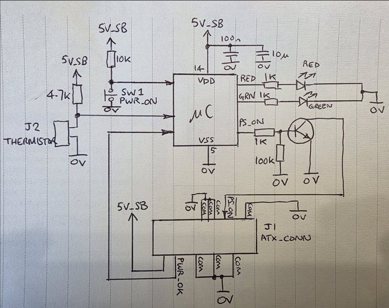
Here's a little circuit I've developed to operate an ATX PSU with a single push-button instead of a toggle or slide switch.

image

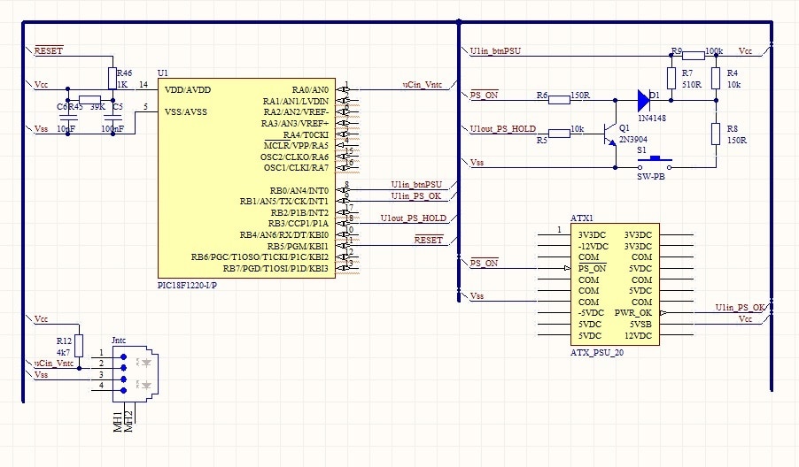
The heart of the circuit is a few components including a diode and a transistor.  I'm wanting to power the MCU from the standby 5volt line, can anyone here advise me what current this pin is normally able to source and is it usually held stable or does it power down periodically?

For those who'd like to understand more about the circuit I'm providing a link to my Wix project page: ATX power supply remote start with single push button. | Blokeystuff

  • Sign in to reply
  • Cancel

Top Replies

  • shabaz
    shabaz 3 days ago +1
    Hi, The circuit can't work as it stands, because there's no ground (or 0V or Vss or whatever it's desired to be called) connection to the ATX connector. You've also got signals going into the bus with…
  • koshkb
    koshkb 3 days ago +1 suggested
    Usually the +5VSB pin is capable supply 2 amps os more, check the labet on the PSU.
  • shabaz
    shabaz 1 day ago in reply to Stuart_S +1
    Hi, I'm not going to breadboard it; unfortunately, I don't have time for that. If desired, you could simplify the circuit, as shown here. All microcontroller inputs are on the left, and all outputs…
Parents
  • shabaz
    0 shabaz 3 days ago

    Hi,

    The circuit can't work as it stands, because there's no ground (or 0V or Vss or whatever it's desired to be called) connection to the ATX connector. You've also got signals going into the bus with no labels, and some signals (such as RedLED and GrnLED) going into the bus with a label but unattached to anything.

    Personally I don't understand the rest of the circuit (and the explanation was hard for me to follow) but if that is tested and working then I have no comment. The web page is silent on whether this is a tested and working project, or something in-progress and still to be tested.

    On the schematic, it's worth restricting bus usage for grouping things with some type of similarity, otherwise it's very hard to follow. For instance, perhaps a bus for the port A signals (RA) and another bus for the port B signals (RB).

    Regarding your 5V standby line question, I don't know the answer (I'd be surprised if google doesn't help here, since ATX supplies are so common), but it's going to be highly likely more than sufficient to power the PIC microcontroller.

    • Cancel
    • Vote Up +1 Vote Down
    • Sign in to reply
    • Verify Answer
    • Cancel
  • Stuart_S
    0 Stuart_S 1 day ago in reply to shabaz

    The circuit works, just add Vss to the COM line on the ATX pins. Did you take the time to breadboard it or try an example on say Multisim or Simetrix?

    • Cancel
    • Vote Up 0 Vote Down
    • Sign in to reply
    • Verify Answer
    • Cancel
  • shabaz
    0 shabaz 1 day ago in reply to Stuart_S

    Hi,

    I'm not going to breadboard it; unfortunately, I don't have time for that.

    If desired, you could simplify the circuit, as shown here. All microcontroller inputs are on the left, and all outputs are on the right side. This circuit puts the ATX supply power-on capability entirely under the control of the microcontroller, i.e. the power-on switch is now only wired to the microcontroller, so the code would need to control the supply based on that. It's a minimal circuit, you may want to add some extra parts, say to filter the standby supply a little bit, but it's a start. I'm not suggesting you scrap your circuit if it works, it's just a data-point about I would have gone about it, (and how I would have drawn the circuit, in this case without the need for buses) if you're looking for ideas. Also, just from habit, I've moved the thermistor so that one end is connected to 0V instead of the positive supply, that's just because I usually find that more convenient, obviously the code would change for that as a result too.

    The symbol I'm using for the microcontroller has, as mentioned, the inputs and outputs on separate sides, that's possible with CAD software by making a copy of the current symbol and then editing it to move the pins.

    image

    • Cancel
    • Vote Up +1 Vote Down
    • Sign in to reply
    • Verify Answer
    • Cancel
Reply
  • shabaz
    0 shabaz 1 day ago in reply to Stuart_S

    Hi,

    I'm not going to breadboard it; unfortunately, I don't have time for that.

    If desired, you could simplify the circuit, as shown here. All microcontroller inputs are on the left, and all outputs are on the right side. This circuit puts the ATX supply power-on capability entirely under the control of the microcontroller, i.e. the power-on switch is now only wired to the microcontroller, so the code would need to control the supply based on that. It's a minimal circuit, you may want to add some extra parts, say to filter the standby supply a little bit, but it's a start. I'm not suggesting you scrap your circuit if it works, it's just a data-point about I would have gone about it, (and how I would have drawn the circuit, in this case without the need for buses) if you're looking for ideas. Also, just from habit, I've moved the thermistor so that one end is connected to 0V instead of the positive supply, that's just because I usually find that more convenient, obviously the code would change for that as a result too.

    The symbol I'm using for the microcontroller has, as mentioned, the inputs and outputs on separate sides, that's possible with CAD software by making a copy of the current symbol and then editing it to move the pins.

    image

    • Cancel
    • Vote Up +1 Vote Down
    • Sign in to reply
    • Verify Answer
    • Cancel
Children
No Data
element14 Community

element14 is the first online community specifically for engineers. Connect with your peers and get expert answers to your questions.

  • Members
  • Learn
  • Technologies
  • Challenges & Projects
  • Products
  • Store
  • About Us
  • Feedback & Support
  • FAQs
  • Terms of Use
  • Privacy Policy
  • Legal and Copyright Notices
  • Sitemap
  • Cookies

An Avnet Company © 2025 Premier Farnell Limited. All Rights Reserved.

Premier Farnell Ltd, registered in England and Wales (no 00876412), registered office: Farnell House, Forge Lane, Leeds LS12 2NE.

ICP 备案号 10220084.

Follow element14

  • X
  • Facebook
  • linkedin
  • YouTube