


Introduction
XMP-2 is a small mobile platform intended for robotics experiments. It is constructed from aluminium and uses a few methods described earlier for high accuracy on smooth surfaces.
Check out the coin test in this video: XMP-2 Practice Run
It is not always possible to build hardware at the same time as the software, and much time can be saved if software developers can use a simulated robot instead of real hardware.
A free simulation package called Gazebo was previously briefly investigated and it allows a 3D robot model to be created and then physics based interactions can occur.
Now it was time to attempt to simulate XMP-2 and see how the simulation could be controlled as if it were real hardware.

Building XMP-2 (Virtually)
Gazebo has a graphical model editor but it was actually easier to just type the description of they physical XMP-2 into a text file. You just need to be handy with a calculator so that you can calculate centres of the primitive blocks/elements you have available to construct the model.
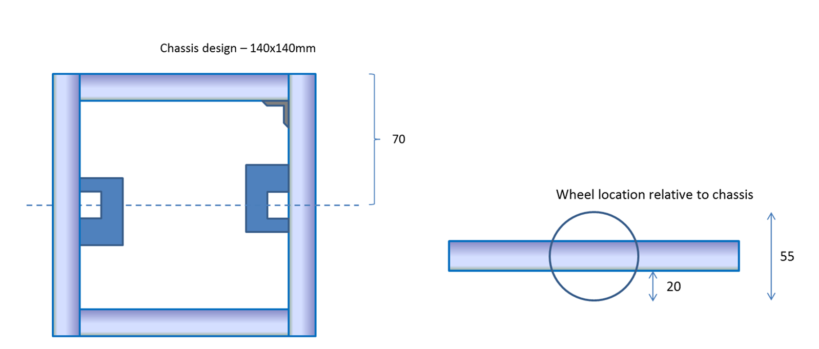
I started with the square shaped aluminium frame. The real XMP-2 frame measures 140x140mm so I punched in exactly these values into the model.
Next I needed to model the castors. There are two on XMP-2. They were constructed from a cylinder and a sphere for the ball bearing.
For the wheels I used the cylinder primitive shape again. Since I had datasheets for all parts, it was very easy to look up dimensions so that the virtual XMP-2 would be identical in size. If you're building any robot it is a good idea to keep drawings with dimensions on them:
In order for Gazebo to understand which axis the wheels rotate about, a further two elements are needed, one per wheel. I didn’t quite understand them in detail, but they appear to work. You will see them in the final model file pasted further below.

Note that for all of the elements described, their position is represented as the co-ordinate at the centre of the primitive.
Once the model file is complete, it can be given a visual inspection using Gazebo as shown in the graphic rendering above - it looks close enough to the actual XMP-2:

Here is the complete text based model of XMP-2. If you are building your own virtual robot then it could be used as a guide to see how to construct it:
<?xml version='1.00'?>
<sdf version='1.4'>
  <model name="XMP-2">
    <static>false</static>
    <link name='chassis'>
      <pose>0 0 .0275 0 0 0</pose>
      <!-- ****** Box ****** -->
      <collision name='collision'>
        <geometry>
          <box>
            <size>.14 .14 .015</size>
          </box>
        </geometry>
      </collision>

      <visual name='visual'>
        <geometry>
          <box>
            <size>.14 .14 .015</size>
          </box>
        </geometry>
      </visual>


      <collision name='casterbase_collision1'>
        <pose>-0.0625 0 -0.01575 0 0 0</pose>
        <geometry>
          <cylinder>
            <radius>0.01</radius>
            <length>0.0165</length>
          </cylinder>
        </geometry>
      </collision>

      <visual name='casterbase_visual1'>
        <pose>-0.0625 0 -0.01575 0 0 0</pose>
        <geometry>
          <cylinder>
            <radius>0.01</radius>
            <length>0.0165</length>
          </cylinder>
        </geometry>
      </visual>


      <collision name='casterbase_collision2'>
        <pose>0.0625 0 -0.01575 0 0 0</pose>
        <geometry>
          <cylinder>
            <radius>0.01</radius>
            <length>0.0165</length>
          </cylinder>
        </geometry>
      </collision>

      <visual name='casterbase_visual2'>
        <pose>0.0625 0 -0.01575 0 0 0</pose>
        <geometry>
          <cylinder>
            <radius>0.01</radius>
            <length>0.0165</length>
          </cylinder>
        </geometry>
      </visual>


      <!-- ****** Caster ****** -->
      <collision name='caster_collision1'>
        <pose>-0.0625 0 -0.024325 0 0 0</pose>
        <geometry>
            <sphere>
            <radius>0.00635</radius>
          </sphere>
        </geometry>

        <surface>
          <friction>
            <ode>
              <mu>0</mu>
              <mu2>0</mu2>
              <slip1>1.0</slip1>
              <slip2>1.0</slip2>
            </ode>
          </friction>
        </surface>
      </collision>

      <visual name='caster_visual1'>
        <pose>-0.0625 0 -0.024325 0 0 0</pose>
        <geometry>
          <sphere>
            <radius>0.00635</radius>
          </sphere>
        </geometry>
      </visual>
      <collision name='caster_collision2'>
        <pose>0.0625 0 -0.024325 0 0 0</pose>
        <geometry>
            <sphere>
            <radius>0.00635</radius>
          </sphere>
        </geometry>

        <surface>
          <friction>
            <ode>
              <mu>0</mu>
              <mu2>0</mu2>
              <slip1>1.0</slip1>
              <slip2>1.0</slip2>
            </ode>
          </friction>
        </surface>
      </collision>

      <visual name='caster_visual2'>
        <pose>0.0625 0 -0.024325 0 0 0</pose>
        <geometry>
          <sphere>
            <radius>0.00635</radius>
          </sphere>
        </geometry>
      </visual>
    </link>


    <!-- ****** Wheels ****** -->
    <link name="left_wheel">
      <pose>0 0.075 0.0275 0 1.5707 1.5707</pose>
      <collision name="collision">
        <geometry>
          <cylinder>
            <radius>0.0275</radius>
            <length>0.008</length>
          </cylinder>
        </geometry>
      </collision>
      <visual name="visual">
        <geometry>
          <cylinder>
            <radius>0.0275</radius>
            <length>0.008</length>
          </cylinder>
        </geometry>
      </visual>
    </link>
    <link name="right_wheel">
      <pose>0 -0.075 0.0275 0 1.5707 1.5707</pose>
      <collision name="collision">
        <geometry>
          <cylinder>
            <radius>0.0275</radius>
            <length>0.008</length>
          </cylinder>
        </geometry>
      </collision>
      <visual name="visual">
        <geometry>
          <cylinder>
            <radius>0.0275</radius>
            <length>0.008</length>
          </cylinder>
        </geometry>
      </visual>
    </link>

    <!-- ****** Hinge Joints for Wheels ****** -->
    <joint type="revolute" name="left_wheel_hinge">
        <pose>0 0 -0.03 0 0 0</pose>
        <child>left_wheel</child>
        <parent>chassis</parent>
        <axis>
          <xyz>0 1 0</xyz>
        </axis>
      </joint>
      <joint type="revolute" name="right_wheel_hinge">
        <pose>0 0 0.03 0 0 0</pose>
        <child>right_wheel</child>
        <parent>chassis</parent>
        <axis>
          <xyz>0 1 0</xyz>
        </axis>
      </joint>

      <plugin name="model-plugin" filename="build/libmodel-plugin.so"/>
  </model>
</sdf>
To use the model, create a folder in ~/.gazebo/models called xmp-2 and save the content in a file there (i.e. in ~/.gazebo/models/xmp-2) called model.sdf
Next create a configuration file in the same folder called model.config containing this:
<?xml version="1.0"?>
<model>
  <name>XMP-2</name>
  <version>1.0</version>
  <sdf version='1.4'>model.sdf</sdf>

  <author>
   <name>shabaz</name>
   <email>shabaz</email>
  </author>

  <description>
    XMP-2 XMOS Mobile Platform 2
  </description>
</model>
You should now be able to run Gazebo (as described in the earlier blog post) and view XMP-2 and exert force on it in any direction using the graphical user interface. Once you have added XMP-2 to the world view, select 'Save As' from the Gazebo menu and save the XMP-2 robot inside the world view as a file called xmp-2-world.world
The file can be saved in a custom folder off your home folder. For example, call the new folder gazebo_work
If you view the file in an editor, it will look something like this (or just use this version if you prefer):
<sdf version='1.5'>
  <world name='default'>
    <light name='sun' type='directional'>
      <cast_shadows>1</cast_shadows>
      <pose>0 0 10 0 -0 0</pose>
      <diffuse>0.8 0.8 0.8 1</diffuse>
      <specular>0.2 0.2 0.2 1</specular>
      <attenuation>
        <range>1000</range>
        <constant>0.9</constant>
        <linear>0.01</linear>
        <quadratic>0.001</quadratic>
      </attenuation>
      <direction>-0.5 0.1 -0.9</direction>
    </light>
    <model name='ground_plane'>
      <static>1</static>
      <link name='link'>
        <collision name='collision'>
          <geometry>
            <plane>
              <normal>0 0 1</normal>
              <size>100 100</size>
            </plane>
          </geometry>
          <surface>
            <friction>
              <ode>
                <mu>100</mu>
                <mu2>50</mu2>
              </ode>
            </friction>
            <contact>
              <ode/>
            </contact>
            <bounce/>
          </surface>
          <max_contacts>10</max_contacts>
        </collision>
        <visual name='visual'>
          <cast_shadows>0</cast_shadows>
          <geometry>
            <plane>
              <normal>0 0 1</normal>
              <size>100 100</size>
            </plane>
          </geometry>
          <material>
            <script>
              <uri>file://media/materials/scripts/gazebo.material</uri>
              <name>Gazebo/Grey</name>
            </script>
          </material>
        </visual>
        <self_collide>0</self_collide>
        <kinematic>0</kinematic>
        <gravity>1</gravity>
      </link>
    </model>
    <physics name='default_physics' default='0' type='ode'>
      <max_step_size>0.001</max_step_size>
      <real_time_factor>1</real_time_factor>
      <real_time_update_rate>1000</real_time_update_rate>
      <gravity>0 0 -9.8</gravity>
      <magnetic_field>6e-06 2.3e-05 -4.2e-05</magnetic_field>
    </physics>
    <scene>
      <ambient>0.4 0.4 0.4 1</ambient>
      <background>0.7 0.7 0.7 1</background>
      <shadows>1</shadows>
    </scene>
    <spherical_coordinates>
      <surface_model>EARTH_WGS84</surface_model>
      <latitude_deg>0</latitude_deg>
      <longitude_deg>0</longitude_deg>
      <elevation>0</elevation>
      <heading_deg>0</heading_deg>
    </spherical_coordinates>
    <model name='XMP-2_0'>
      <static>0</static>
      <link name='chassis'>
        <pose>0 0 0.0275 0 -0 0</pose>
        <collision name='collision'>
          <geometry>
            <box>
              <size>0.14 0.14 0.015</size>
            </box>
          </geometry>
          <max_contacts>10</max_contacts>
          <surface>
            <contact>
              <ode/>
            </contact>
            <bounce/>
            <friction>
              <ode/>
            </friction>
          </surface>
        </collision>
        <visual name='visual'>
          <geometry>
            <box>
              <size>0.14 0.14 0.015</size>
            </box>
          </geometry>
        </visual>
        <collision name='casterbase_collision1'>
          <pose>-0.0625 0 -0.01575 0 -0 0</pose>
          <geometry>
            <cylinder>
              <radius>0.01</radius>
              <length>0.0165</length>
            </cylinder>
          </geometry>
          <max_contacts>10</max_contacts>
          <surface>
            <contact>
              <ode/>
            </contact>
            <bounce/>
            <friction>
              <ode/>
            </friction>
          </surface>
        </collision>
        <visual name='casterbase_visual1'>
          <pose>-0.0625 0 -0.01575 0 -0 0</pose>
          <geometry>
            <cylinder>
              <radius>0.01</radius>
              <length>0.0165</length>
            </cylinder>
          </geometry>
        </visual>
        <collision name='casterbase_collision2'>
          <pose>0.0625 0 -0.01575 0 -0 0</pose>
          <geometry>
            <cylinder>
              <radius>0.01</radius>
              <length>0.0165</length>
            </cylinder>
          </geometry>
          <max_contacts>10</max_contacts>
          <surface>
            <contact>
              <ode/>
            </contact>
            <bounce/>
            <friction>
              <ode/>
            </friction>
          </surface>
        </collision>
        <visual name='casterbase_visual2'>
          <pose>0.0625 0 -0.01575 0 -0 0</pose>
          <geometry>
            <cylinder>
              <radius>0.01</radius>
              <length>0.0165</length>
            </cylinder>
          </geometry>
        </visual>
        <collision name='caster_collision1'>
          <pose>-0.0625 0 -0.024325 0 -0 0</pose>
          <geometry>
            <sphere>
              <radius>0.00635</radius>
            </sphere>
          </geometry>
          <surface>
            <friction>
              <ode>
                <mu>0</mu>
                <mu2>0</mu2>
                <slip1>1</slip1>
                <slip2>1</slip2>
              </ode>
            </friction>
            <contact>
              <ode/>
            </contact>
            <bounce/>
          </surface>
          <max_contacts>10</max_contacts>
        </collision>
        <visual name='caster_visual1'>
          <pose>-0.0625 0 -0.024325 0 -0 0</pose>
          <geometry>
            <sphere>
              <radius>0.00635</radius>
            </sphere>
          </geometry>
        </visual>
        <collision name='caster_collision2'>
          <pose>0.0625 0 -0.024325 0 -0 0</pose>
          <geometry>
            <sphere>
              <radius>0.00635</radius>
            </sphere>
          </geometry>
          <surface>
            <friction>
              <ode>
                <mu>0</mu>
                <mu2>0</mu2>
                <slip1>1</slip1>
                <slip2>1</slip2>
              </ode>
            </friction>
            <contact>
              <ode/>
            </contact>
            <bounce/>
          </surface>
          <max_contacts>10</max_contacts>
        </collision>
        <visual name='caster_visual2'>
          <pose>0.0625 0 -0.024325 0 -0 0</pose>
          <geometry>
            <sphere>
              <radius>0.00635</radius>
            </sphere>
          </geometry>
        </visual>
        <self_collide>0</self_collide>
        <inertial>
          <inertia>
            <ixx>1</ixx>
            <ixy>0</ixy>
            <ixz>0</ixz>
            <iyy>1</iyy>
            <iyz>0</iyz>
            <izz>1</izz>
          </inertia>
          <mass>1</mass>
        </inertial>
        <kinematic>0</kinematic>
        <gravity>1</gravity>
      </link>
      <link name='left_wheel'>
        <pose>0 0.075 0.0275 -0 1.5707 1.5707</pose>
        <collision name='collision'>
          <geometry>
            <cylinder>
              <radius>0.0275</radius>
              <length>0.008</length>
            </cylinder>
          </geometry>
          <max_contacts>10</max_contacts>
          <surface>
            <contact>
              <ode/>
            </contact>
            <bounce/>
            <friction>
              <ode/>
            </friction>
          </surface>
        </collision>
        <visual name='visual'>
          <geometry>
            <cylinder>
              <radius>0.0275</radius>
              <length>0.008</length>
            </cylinder>
          </geometry>
        </visual>
        <self_collide>0</self_collide>
        <inertial>
          <inertia>
            <ixx>1</ixx>
            <ixy>0</ixy>
            <ixz>0</ixz>
            <iyy>1</iyy>
            <iyz>0</iyz>
            <izz>1</izz>
          </inertia>
          <mass>1</mass>
        </inertial>
        <kinematic>0</kinematic>
        <gravity>1</gravity>
      </link>
      <link name='right_wheel'>
        <pose>0 -0.075 0.0275 -0 1.5707 1.5707</pose>
        <collision name='collision'>
          <geometry>
            <cylinder>
              <radius>0.0275</radius>
              <length>0.008</length>
            </cylinder>
          </geometry>
          <max_contacts>10</max_contacts>
          <surface>
            <contact>
              <ode/>
            </contact>
            <bounce/>
            <friction>
              <ode/>
            </friction>
          </surface>
        </collision>
        <visual name='visual'>
          <geometry>
            <cylinder>
              <radius>0.0275</radius>
              <length>0.008</length>
            </cylinder>
          </geometry>
        </visual>
        <self_collide>0</self_collide>
        <inertial>
          <inertia>
            <ixx>1</ixx>
            <ixy>0</ixy>
            <ixz>0</ixz>
            <iyy>1</iyy>
            <iyz>0</iyz>
            <izz>1</izz>
          </inertia>
          <mass>1</mass>
        </inertial>
        <kinematic>0</kinematic>
        <gravity>1</gravity>
      </link>
      <joint name='left_wheel_hinge' type='revolute'>
        <pose>0 0 -0.03 0 -0 0</pose>
        <child>left_wheel</child>
        <parent>chassis</parent>
        <axis>
          <xyz>0 1 0</xyz>
          <use_parent_model_frame>1</use_parent_model_frame>
          <limit>
            <lower>-1e+16</lower>
            <upper>1e+16</upper>
          </limit>
          <dynamics>
            <spring_reference>0</spring_reference>
            <spring_stiffness>0</spring_stiffness>
          </dynamics>
        </axis>
      </joint>
      <joint name='right_wheel_hinge' type='revolute'>
        <pose>0 0 0.03 0 -0 0</pose>
        <child>right_wheel</child>
        <parent>chassis</parent>
        <axis>
          <xyz>0 1 0</xyz>
          <use_parent_model_frame>1</use_parent_model_frame>
          <limit>
            <lower>-1e+16</lower>
            <upper>1e+16</upper>
          </limit>
          <dynamics>
            <spring_reference>0</spring_reference>
            <spring_stiffness>0</spring_stiffness>
          </dynamics>
        </axis>
      </joint>
      <plugin name='model-plugin' filename='build/libmodel-plugin.so'/>
      <pose>1 0.403425 0 0 -0 0</pose>
    </model>
    <state world_name='default'>
      <sim_time>159 732000000</sim_time>
      <real_time>161 509335075</real_time>
      <wall_time>1448069945 796721688</wall_time>
      <iterations>159732</iterations>
      <model name='XMP-2_0'>
        <pose>1.00016 0.400351 0.003177 -0.034765 -3e-06 -1e-05</pose>
        <link name='chassis'>
          <pose>1.00016 0.401307 0.030661 -0.034765 -3e-06 -1e-05</pose>
          <velocity>4.1e-05 -0.000304 -0.000415 -0.000522 0.006631 -0.000157</velocity>
          <acceleration>-0 -0 -0.11343 3.13345 1.32683 3.09945</acceleration>
          <wrench>-0 -0 -0.11343 0 -0 0</wrench>
        </link>
        <link name='left_wheel'>
          <pose>1.00016 0.476261 0.028054 2.25893 1.51619 -2.4543</pose>
          <velocity>3.5e-05 -0.000305 -0.000454 -0.000522 0.001552 2e-05</velocity>
          <acceleration>-0.001578 -2.1e-05 -0.114036 -0.00816 0.000758 0.02095</acceleration>
          <wrench>-0.001578 -2.1e-05 -0.114036 0 -0 0</wrench>
        </link>
        <link name='right_wheel'>
          <pose>1.00016 0.326352 0.033267 -2.26498 1.5166 -0.693561</pose>
          <velocity>4.6e-05 -0.000302 -0.000376 -0.000522 -0.001516 0.000127</velocity>
          <acceleration>0.001578 2.1e-05 -0.112823 -0.008159 0.000702 0.020954</acceleration>
          <wrench>0.001578 2.1e-05 -0.112823 0 -0 0</wrench>
        </link>
      </model>
      <model name='ground_plane'>
        <pose>0 0 0 0 -0 0</pose>
        <link name='link'>
          <pose>0 0 0 0 -0 0</pose>
          <velocity>0 0 0 0 -0 0</velocity>
          <acceleration>0 0 0 0 -0 0</acceleration>
          <wrench>0 0 0 0 -0 0</wrench>
        </link>
      </model>
    </state>
    <gui fullscreen='0'>
      <camera name='user_camera'>
        <pose>2.07864 -0.370742 0.357459 0 0.275643 2.35619</pose>
        <view_controller>orbit</view_controller>
        <projection_type>perspective</projection_type>
      </camera>
    </gui>
  </world>
</sdf>
As you can see, the world view file has embedded the XMP-2 model in it entirely. The next step is to develop some software to control the model inside this world view.
Creating a Software Plugin for Controlling the Model
A software plugin in the form of a shared library was created in order to pass instructions into Gazebo about how and where the model is to move.
Firstly, a makefile was created in the same gazebo_work folder created earlier. The file is called CMakeLists.txt and needs to contain the following content:
cmake_minimum_required(VERSION 2.8 FATAL_ERROR)

find_package(gazebo REQUIRED)
include_directories(${GAZEBO_INCLUDE_DIRS})
link_directories(${GAZEBO_LIBRARY_DIRS})
list(APPEND CMAKE_CXX_FLAGS "${GAZEBO_CXX_FLAGS}")

add_library(model-plugin SHARED model-plugin.cc)
target_link_libraries(model-plugin ${GAZEBO_LIBRARIES})

set(CMAKE_CXX_FLAGS "${CMAKE_CXX_FLAGS} ${GAZEBO_CXX_FLAGS}")
The code for the plugin is written in C++ and is shown below. There is a tutorial which covers this in detail. I modified the existing tutorial code such that the code can receive stimulus externally. The code was saved in a file called model-plugin.cc at the same location as the makefile:
#include <boost/bind.hpp>
#include <gazebo/gazebo.hh>
#include <gazebo/physics/physics.hh>
#include <gazebo/common/common.hh>
#include <stdio.h>
#include <iostream>
#include <fstream>
#include <string>

using namespace std;

namespace gazebo
{
  class ModelPush : public ModelPlugin
  {
    public: void Load(physics::ModelPtr _parent, sdf::ElementPtr /*_sdf*/)
    {
      // Store the pointer to the model
      this->model = _parent;


      // Listen to the update event. This event is broadcast every
      // simulation iteration.
      this->updateConnection = event::Events::ConnectWorldUpdateBegin(
          boost::bind(&ModelPush::OnUpdate, this, _1));
    }


    // Called by the world update start event
    public: void OnUpdate(const common::UpdateInfo & /*_info*/)
    {
      ifstream fp;
      string line;
      int cmd=0;
      fp.open("command.txt");
      if (fp.is_open())
      {
        while(getline(fp, line))
        {
          if (line.find("move") != string::npos)
          {
            cmd=1;
          }
        }
        fp.close();
      }
      if (cmd==1)
      {
        // Apply a small linear velocity to the model.
        this->model->SetLinearVel(math::Vector3(.03, 0, 0));
      }
    }


    // Pointer to the model
    private: physics::ModelPtr model;


    // Pointer to the update event connection
    private: event::ConnectionPtr updateConnection;
  };


  // Register this plugin with the simulator
  GZ_REGISTER_MODEL_PLUGIN(ModelPush)
}
Now create a build folder in the same location (so the path is now ~/gazebo_work/build )
and go inside the build folder and type the following (Note: You may need to install cmake if your Linux distribution does not alreagy have this, e.g. type as root user apt-get install cmake ):
cmake ../
make
After a while the build process will have resulted in a file called libmodel-plugin.so
Just as an fyi, the file name matches a name which was originally typed in the model.sdl file too, and it became part of the xmp-2-world.world file too. If you examine those files you'll see it in a line looking like this:
<plugin name="model-plugin" filename="build/libmodel-plugin.so"/>
The C++ code (model-plugin.cc) shown above contains some modifications I made to allow for communications.
There are many ways of doing this, so one can use their own ideas/initiative. For now I chose a very simple file based method. A socket interface would be a good method too.
My simple method merely checks for the presence of a file called command.txt and executes whatever command is written in that file. It is possible to modify the file contents on-the-fly using either manual typing or under the control of some other program. You can see on line 40 that it checks for the text 'move'. It could be expanded greatly.
Why is this useful? Well the other program could be taking input from a serial interface or USB device! The serial interface could be from (say) a Raspberry Pi. This means it is possible to develop robot software to run on the single board computer (SBC) of your choice, and simulate the robot on the PC in order to test the software. The software on the SBC would have no idea if it were a real robot or a simulated robot connected to the serial port.
If you wanted to sell robots then it could potentially allow people to program and try out the simulated robot, and purchase the real thing if they were satisfied it met their need. In other words the simulation would become a sales tool.
Or if you only had one robot but wanted to see how a whole army of them would behave then you could just instantiate multiple copies of the model and multiple copies of the robot software.
Running The Virtual Robot
Close down Gazebo if it is currently running, and then in a terminal type the following to start the simulation in paused mode:
gzserver --verbose -u xmp-2-world.world
In another terminal window bring up the graphical user interface (GUI) by typing the following:
gzclient
Now click the 'Play' button at the bottom of the GUI in order to run the simulation!
Nothing will happen, because the code is waiting for a command to appear in the command.txt file mentioned earlier, as designed.
So, in a third terminal window or using an editor of your choice, create a command.txt file in ~/gazebo_work and type the word
'move' in it and save the file. As soon as the file is saved the virtual robot will begin moving! To stop it, delete the line and save the file again. This of course is just a simple demo so scale it as desired with more functionality.
The video here shows the simulation being run:
To quit out, exit the GUI from the menu and then type Ctrl-C on the terminal running the simulation. It will take 15 seconds or so to quit.
Summary
It turns out to be fairly easy to construct a model and then drive it using external control in a virtual world. There could be many uses for this. This has been just a brief post and some more understanding is needed to more accurately simulate the physics of the real robot in the virtual world.
Although the code here uses a text file to control the virtual robot, it would be extremely easy to extend the control over serial or USB. This allows real world sensors and external single board computers to provide data and intelligence to control the virtual robot.
Top Comments
-

DAB
-
Cancel
-
Vote Up
+2
Vote Down
-
-
Sign in to reply
-
More
-
Cancel
-

mcb1
in reply to DAB
-
Cancel
-
Vote Up
+1
Vote Down
-
-
Sign in to reply
-
More
-
Cancel
-

balearicdynamics
in reply to mcb1
-
Cancel
-
Vote Up
+2
Vote Down
-
-
Sign in to reply
-
More
-
Cancel
-

DAB
in reply to mcb1
-
Cancel
-
Vote Up
+3
Vote Down
-
-
Sign in to reply
-
More
-
Cancel
-

balearicdynamics
in reply to DAB
-
Cancel
-
Vote Up
+1
Vote Down
-
-
Sign in to reply
-
More
-
Cancel
Comment-

balearicdynamics
in reply to DAB
-
Cancel
-
Vote Up
+1
Vote Down
-
-
Sign in to reply
-
More
-
Cancel
Children