element14 Community
element14 Community
    Register Log In
  • Site
  • Search
  • Log In Register
  • Community Hub
    Community Hub
    • What's New on element14
    • Feedback and Support
    • Benefits of Membership
    • Personal Blogs
    • Members Area
    • Achievement Levels
  • Learn
    Learn
    • Ask an Expert
    • eBooks
    • element14 presents
    • Learning Center
    • Tech Spotlight
    • STEM Academy
    • Webinars, Training and Events
    • Learning Groups
  • Technologies
    Technologies
    • 3D Printing
    • FPGA
    • Industrial Automation
    • Internet of Things
    • Power & Energy
    • Sensors
    • Technology Groups
  • Challenges & Projects
    Challenges & Projects
    • Design Challenges
    • element14 presents Projects
    • Project14
    • Arduino Projects
    • Raspberry Pi Projects
    • Project Groups
  • Products
    Products
    • Arduino
    • Avnet & Tria Boards Community
    • Dev Tools
    • Manufacturers
    • Multicomp Pro
    • Product Groups
    • Raspberry Pi
    • RoadTests & Reviews
  • About Us
  • Store
    Store
    • Visit Your Store
    • Choose another store...
      • Europe
      •  Austria (German)
      •  Belgium (Dutch, French)
      •  Bulgaria (Bulgarian)
      •  Czech Republic (Czech)
      •  Denmark (Danish)
      •  Estonia (Estonian)
      •  Finland (Finnish)
      •  France (French)
      •  Germany (German)
      •  Hungary (Hungarian)
      •  Ireland
      •  Israel
      •  Italy (Italian)
      •  Latvia (Latvian)
      •  
      •  Lithuania (Lithuanian)
      •  Netherlands (Dutch)
      •  Norway (Norwegian)
      •  Poland (Polish)
      •  Portugal (Portuguese)
      •  Romania (Romanian)
      •  Russia (Russian)
      •  Slovakia (Slovak)
      •  Slovenia (Slovenian)
      •  Spain (Spanish)
      •  Sweden (Swedish)
      •  Switzerland(German, French)
      •  Turkey (Turkish)
      •  United Kingdom
      • Asia Pacific
      •  Australia
      •  China
      •  Hong Kong
      •  India
      •  Korea (Korean)
      •  Malaysia
      •  New Zealand
      •  Philippines
      •  Singapore
      •  Taiwan
      •  Thailand (Thai)
      • Americas
      •  Brazil (Portuguese)
      •  Canada
      •  Mexico (Spanish)
      •  United States
      Can't find the country/region you're looking for? Visit our export site or find a local distributor.
  • Translate
  • Profile
  • Settings
Robotics
  • Technologies
  • More
Robotics
Forum H-Bridge Problems
  • Blog
  • Forum
  • Documents
  • Quiz
  • Events
  • Polls
  • Members
  • Mentions
  • Sub-Groups
  • Tags
  • More
  • Cancel
  • New
Join Robotics to participate - click to join for free!
Actions
  • Share
  • More
  • Cancel
Forum Thread Details
  • Replies 8 replies
  • Subscribers 63 subscribers
  • Views 1905 views
  • Users 0 members are here
  • motor_circuits
Related

H-Bridge Problems

Former Member
Former Member over 12 years ago

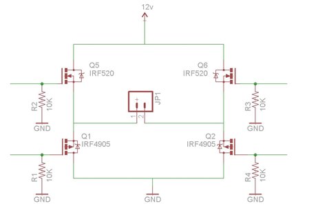
Hello! So I'm working on a project which I'm trying to control 12V motors which draws 4.3-4.5A. I thought that if I used power mosfets (IRF5210 and IRF520) I will be able to control it using an Aarduino board. When I connected my motor, hbridge, arduino pins to the gates of my hbridge and my 12V 9H battery together, my motor does not turn and my transistors keep burning. What did I do wrong with my circuit. Here's the original schematic. Thanks guys!

image

  • Sign in to reply
  • Cancel

Top Replies

  • michaelkellett
    michaelkellett over 12 years ago in reply to shabaz +1
    This is a really bad motor driver circuit. Even if you make the corrections others have suggested (P channel FETs at the top, R2 and R3 to +12V) then the Arduino outputs, even if open drain, are not rated…
Parents
  • gdstew
    gdstew over 12 years ago

    Are you running a program on the Arduino to make sure the outputs are not turning on all the transistors at once before you connect the 12V ? If not this could

    produce a short between 12V and ground across the transistors which would cause problems. Are you using the Arduino PWM library ? If I remember correctly

    the Arduino PWM library code turns the outputs off for the programmed time interval (outputs start out high) which is inverted from what you would normally

    expect. So if you start out with the lowest value for the PWM time (0x00) the outputs would always be on.

    • Cancel
    • Vote Up 0 Vote Down
    • Sign in to reply
    • Cancel
  • Former Member
    Former Member over 12 years ago in reply to gdstew

    Here was the original code. Control1 was connected to Q5, Control2 was connected to Q1, Control3 was connected to Q6, and Control4 was connected to Q2. Although I connected each transistor gate to a PWM pin on the Arduino, I used digitalWrites in my code.


    int control1=3;

    int control2=5;

    int control3=6;

    int control4=10;


    void setup()

    {

      pinMode(control1,OUTPUT);

      pinMode(control2,OUTPUT);

      pinMode(control3,OUTPUT);

      pinMode(control4,OUTPUT);

    }


    void loop()

    {

      digitalWrite(control1,LOW);

      digitalWrite(control2,LOW);

      digitalWrite(control3,HIGH);

      digitalWrite(control4,HIGH);

      while(1);

    }

    • Cancel
    • Vote Up 0 Vote Down
    • Sign in to reply
    • Cancel
  • gdstew
    gdstew over 12 years ago in reply to Former Member

    Sorry I had to adjust myself to you using P and N channel MOSFETS. I am more used to integrated solutions that normally just use

    N-channel with charge pumps for the the high side gate voltages. Aren't P-channel transistors normally used on the high side and

    N-channel on the low side ? The program looks like it should be working to turn the motor on (Q1 and Q6 on) just make sure its

    running before you connect the power or the motor.  With pull down resistors on the P-channel inputs the transistors will be on if

    the Arduino is not actively pulling them high. I'm not sure if this is what you want or not.

    • Cancel
    • Vote Up 0 Vote Down
    • Sign in to reply
    • Cancel
  • Former Member
    Former Member over 12 years ago in reply to gdstew

    I have the P Channels on the high side, and N channels on the low side. I thought that by setting pull down resistors on all of the transistors, the motor will constantly be off until the Arduino apply voltage at the gates.

    • Cancel
    • Vote Up 0 Vote Down
    • Sign in to reply
    • Cancel
  • shabaz
    shabaz over 12 years ago in reply to Former Member

    Hi David,


    Unfortunately the circuit as shown won't work, because as you say, the P-ch should be at the top, and N-ch at the bottom, however with MOSFETs, the arrow sticking out signifies P-ch. Basically, the top and bottom MOSFETs need swapping round.

    Once that's done, have R2 and R3 going to the same supply as the motors, not to ground. Then, ensure that the microcontroller outputs are 'open drain' types for the top two devices (personally I would use a small resistor in series with the gate too - not too high, maybe 47ohms or so.

    This should get you some way toward getting this going. There are further refinements you could do, but the adjustments described above will get it working. Personally I would stick an inductance in series with the motor too.

    The built-in diodes should be ok, although not all devices specify if they will be fine (so some people use external schottky diodes too). I think you may be fine.

    • Cancel
    • Vote Up 0 Vote Down
    • Sign in to reply
    • Cancel
  • Former Member
    Former Member over 12 years ago in reply to shabaz

    I thought by setting pull down resistors on each gate sets the transistor initially off. Also, I was using 1/16 watt resistors. If I have to use pull resistors connected to a 12 9AH battery, I will need to replace the resistors with higher power rated resistors.


    I'll make sure to try this out and see what happens. Thanks guys!

    • Cancel
    • Vote Up 0 Vote Down
    • Sign in to reply
    • Cancel
  • shabaz
    shabaz over 12 years ago in reply to Former Member

    Hi David,


    The gates consume no current (to a first-level approximation) so 1/16W resistors are fine. (Besides, the high resistance (10k) means that 1/16W won't be exceeded).

    This circuit may still not be ideal  - the N-ch MOSFETs may not fully turn on (the motor will work, but may not run at full power). This one would be more ideal, and

    is in a TO-220 package too.

    • Cancel
    • Vote Up 0 Vote Down
    • Sign in to reply
    • Cancel
Reply
  • shabaz
    shabaz over 12 years ago in reply to Former Member

    Hi David,


    The gates consume no current (to a first-level approximation) so 1/16W resistors are fine. (Besides, the high resistance (10k) means that 1/16W won't be exceeded).

    This circuit may still not be ideal  - the N-ch MOSFETs may not fully turn on (the motor will work, but may not run at full power). This one would be more ideal, and

    is in a TO-220 package too.

    • Cancel
    • Vote Up 0 Vote Down
    • Sign in to reply
    • Cancel
Children
  • michaelkellett
    michaelkellett over 12 years ago in reply to shabaz

    This is  a really bad motor driver circuit. Even if you make the corrections others have suggested (P channel FETs at the top, R2 and R3 to +12V) then the Arduino outputs, even if open drain, are not rated for 12V so you'll damage the Arduino. If you get round that by buffering the Arduino outputs then you still have the issue that there is no dead time (time when all the FETs are off as you switch) and no "shoot through" protection (a way of ensuring that a top FET and a bottom FET are never both turned on at once). On top of that you need more gate volts (10 not 5) to turn on the FETs properly and you should have schottky diodes across each FET to catch reverse voltage when switching off. Then you need some capacitors across the power supply.


    You can get almost everything on one chip but it's in a "difficult" package - ST VNH3SP30TR (Farnell 1909372). An easier part but only just up to your spec is the Infineon TLE5205-2 (Farnell 2215546) in a TO 220 package.


    MK

    • Cancel
    • Vote Up +1 Vote Down
    • Sign in to reply
    • Cancel
element14 Community

element14 is the first online community specifically for engineers. Connect with your peers and get expert answers to your questions.

  • Members
  • Learn
  • Technologies
  • Challenges & Projects
  • Products
  • Store
  • About Us
  • Feedback & Support
  • FAQs
  • Terms of Use
  • Privacy Policy
  • Legal and Copyright Notices
  • Sitemap
  • Cookies

An Avnet Company © 2025 Premier Farnell Limited. All Rights Reserved.

Premier Farnell Ltd, registered in England and Wales (no 00876412), registered office: Farnell House, Forge Lane, Leeds LS12 2NE.

ICP 备案号 10220084.

Follow element14

  • X
  • Facebook
  • linkedin
  • YouTube