element14 Community
element14 Community
    Register Log In
  • Site
  • Search
  • Log In Register
  • Community Hub
    Community Hub
    • What's New on element14
    • Feedback and Support
    • Benefits of Membership
    • Personal Blogs
    • Members Area
    • Achievement Levels
  • Learn
    Learn
    • Ask an Expert
    • eBooks
    • element14 presents
    • Learning Center
    • Tech Spotlight
    • STEM Academy
    • Webinars, Training and Events
    • Learning Groups
  • Technologies
    Technologies
    • 3D Printing
    • FPGA
    • Industrial Automation
    • Internet of Things
    • Power & Energy
    • Sensors
    • Technology Groups
  • Challenges & Projects
    Challenges & Projects
    • Design Challenges
    • element14 presents Projects
    • Project14
    • Arduino Projects
    • Raspberry Pi Projects
    • Project Groups
  • Products
    Products
    • Arduino
    • Avnet & Tria Boards Community
    • Dev Tools
    • Manufacturers
    • Multicomp Pro
    • Product Groups
    • Raspberry Pi
    • RoadTests & Reviews
  • About Us
  • Store
    Store
    • Visit Your Store
    • Choose another store...
      • Europe
      •  Austria (German)
      •  Belgium (Dutch, French)
      •  Bulgaria (Bulgarian)
      •  Czech Republic (Czech)
      •  Denmark (Danish)
      •  Estonia (Estonian)
      •  Finland (Finnish)
      •  France (French)
      •  Germany (German)
      •  Hungary (Hungarian)
      •  Ireland
      •  Israel
      •  Italy (Italian)
      •  Latvia (Latvian)
      •  
      •  Lithuania (Lithuanian)
      •  Netherlands (Dutch)
      •  Norway (Norwegian)
      •  Poland (Polish)
      •  Portugal (Portuguese)
      •  Romania (Romanian)
      •  Russia (Russian)
      •  Slovakia (Slovak)
      •  Slovenia (Slovenian)
      •  Spain (Spanish)
      •  Sweden (Swedish)
      •  Switzerland(German, French)
      •  Turkey (Turkish)
      •  United Kingdom
      • Asia Pacific
      •  Australia
      •  China
      •  Hong Kong
      •  India
      •  Korea (Korean)
      •  Malaysia
      •  New Zealand
      •  Philippines
      •  Singapore
      •  Taiwan
      •  Thailand (Thai)
      • Americas
      •  Brazil (Portuguese)
      •  Canada
      •  Mexico (Spanish)
      •  United States
      Can't find the country/region you're looking for? Visit our export site or find a local distributor.
  • Translate
  • Profile
  • Settings
Robotics
  • Technologies
  • More
Robotics
Forum I am interested in a circuit board to control a two digit 7 segment LED.  Information will be coming from my software.
  • Blog
  • Forum
  • Documents
  • Quiz
  • Events
  • Polls
  • Members
  • Mentions
  • Sub-Groups
  • Tags
  • More
  • Cancel
  • New
Join Robotics to participate - click to join for free!
Actions
  • Share
  • More
  • Cancel
Forum Thread Details
  • State Suggested Answer
  • Replies 29 replies
  • Answers 1 answer
  • Subscribers 66 subscribers
  • Views 2813 views
  • Users 0 members are here
  • frontpage
Related

I am interested in a circuit board to control a two digit 7 segment LED.  Information will be coming from my software.

Former Member
Former Member over 11 years ago

I am interested in a circuit board to control a two digit 7 segment LED.  Information will be coming from my software.
I will need the circuit board to show a number (up to 2 digits) and to be able to also have a push button when pressed to turn off the 7 segment LED displaced. 

The quantity of the same board will be from 250 up to 1000 boards.


Thanks,

Tim Cloninger

timcloninger@cs.com

  • Sign in to reply
  • Cancel

Top Replies

  • michaelkellett
    michaelkellett over 11 years ago +1
    What is the software running on and how will it interface with the display board. MK
  • michaelkellett
    michaelkellett over 11 years ago in reply to Former Member +1
    I think you will need a custom board to keep this as cheap as possible but it may still cost you a fair bit. It will cost much less if you assemble the display boards yourself. Each board needs to be addressable…
  • Robert Peter Oakes
    Robert Peter Oakes over 11 years ago +1
    Another thought could be this http://www.sqlskills.com/blogs/paulselec/post/arduino-cascading-shift-registers-to-drive-7-segment-displays.aspx , or based on it anyway, it uses a serial in, serial out mechanism…
  • michaelkellett
    0 michaelkellett over 11 years ago in reply to Robert Peter Oakes

    @Peter and Don and Douglas


    It needs a micro on each display because it needs intelligence on each display. The shift register solutions won't scale to 1000 devices and the clock and data lines can't be emc proofed. The LED driver chips don't support the button and all the shift register systems are addressed by position on the chain so that the system is um-maintainable.


    It can be done with UART style comms (NOT RS232 because the hardware must be different.) Each module needs a unique address (can be coded by dil switch or solder link/track cut). All the displays listen all the time, the PC sends out addressed commands so only one display responds. It periodically asks display which are on of their buttons have been pressed (it's a feature of this system that only a small number of displays are lit at any one time.)

    Just for housekeeping the PC can also poll all the devices on a slow round robin basis just to check that they are happy.


    The timing for this works fine, at 9600 baud it can use, say, 6 byte messages, (2 address, 2 display data, 2 spare) and receive 4 byte messages - so it could interact with about 100 displays per second, max but perhaps more realistically with 25 - 50 allowing for latencies etc.

    There is now way the human picker can keep up with 25 part bin interactions per second so it's easily fast enough.


    So now all we need are three or four wires linking all the devices, all in parallel. Fastest signal is 9600 baud. The receivers on the displays need to be low load so that they can all be driven at once (but that's not too hard at this data rate). The design of the display data driver needs care so that there is no risk of it being permanently asserted because this would jam all the whole system.


    Because each display has a unique code and they are wired in // you can add or remove displays and connect them to the wire at any point in any order and it all still works.


    It's all quite doable but it needs a custom display design.


    MK

    • Cancel
    • Vote Up 0 Vote Down
    • Sign in to reply
    • Verify Answer
    • Cancel
  • Former Member
    0 Former Member over 11 years ago in reply to michaelkellett

    I was initially thinking along the same lines, Michael, about the intelligence required at each display.  To reduce the complexity and to remove the need for two-way communications, the user could enter into the computer that they pulled the parts, at which point the display would get cleared.  If the design needs a clear button at each bin, two way comms may be necessary, for which a small microcontroller would be ideal and pretty easy to set up comms.  Addressing could be jumpers (wire or solder), or even software configurable.  I like your idea for comms, using a full 2 byte address leaves plenty of room for expansion.  This is definitely ideal for a custom display board, though I think some of the cascading options should be able to work since the signals are going to get buffered at each device, up to a certain point.  Multiple buses can be created using I/O expansion as well.  I wonder if there is a market for something like this?  There are already some which are expandable to a degree, but typically nothing more than around 16 devices per bus (at least using in I2C example).

    • Cancel
    • Vote Up 0 Vote Down
    • Sign in to reply
    • Verify Answer
    • Cancel
  • D_Hersey
    0 D_Hersey over 11 years ago

    I don't remember anyone proposing to attempt to do this all with jellybeans.  I'm completely 404 on the etiology of this straw man.  A 'shift register to-the-stars' concept must have just been thrown in to amuse.

    We have an incomplete description of this situation, which leaves us fishing in the dark.

    Not that modulation scheme matters much here, but yeah, RS232 is a differential protocol that requires +15 and -15 volt supplies, but 'RS232 fsk' was shorthand for a scheme where mark and space are represented by two different (inaudible) sound frequencies.  Its tedious to get literal on a guy painting with a broad-brush.

    We don't need to use dip switches or jumpers on our slave boards because they will have some flash or ee memory on them.  We could write the address on the board with a grease pencil.  But yeah, we could and that would save electrical reprogramming, but nowadays we could write a script to do this and just plug the board into a computer for a moment.  Six-to-one, half-a-dozen to the other.


    MK, I presumed that your second paragraph was implied and obvious to anyone, my bad.  I cannot really imagine another scheme.

    This application is nearly trivial and self-authoring from an e- standpoint.  Talking about it to this extent is like hitting a girl.


    Almost any electrical scheme is going to be fast enough, given that we are interfacing to humans.  If the displays are physically proximate this project becomes even easier.  We all make make implicit presumptions about this system given the paucity of specification.  To turn around and cast a scheme with another suite of presumptions, then vet a prior scheme in those terms borders on the cheezy.


    The fervidness of this thread is a mystery to me.  This is a simple, obvious task whatever the intended configuration.  I don't have a horse in this race.  I don't own the warehouse, and I don't traffic in wage-slaves.  I don't need to prove that I understand electronics and computers.  And if I felt that I did, this certainly wouldn't be the project I would use to make that demonstration.  People seem to be arguing about this merely in a quest for centralization.  I certainly don't have any reason to think that I need any further centralization, and if I momentarily think otherwise this is a manifestation of atavistic, antic infantility I should recognize, regret and abjure.


    I feel that I labor to keep these transactions on an adult <> adult level as Eric Berne uses the terms.  I don't feel this effort is being fully reciprocated, a drive toward parent <> child.


    Anyway, I'm resolved not to think about this project any further much less speak of it and write of it lest I see some $.  I think this whole thing is an example of a bunch of really smart people getting together and acting stupidly.

    • Cancel
    • Vote Up 0 Vote Down
    • Sign in to reply
    • Verify Answer
    • Cancel
  • Robert Peter Oakes
    0 Robert Peter Oakes over 11 years ago

    Well, if the cost is not so much of an issue, using a MEGA328 (Arduino) or MSP430 (Launchpad) as a controller, they can drive the LEDs directly but also can interface with a very low cost ethernet adapter based on the ENC chip (Plenty of libraries around). These boards use SPI for coms so do not take too many pins. Next the uController can read switches easily and send randon timed messages back to the master without issues as TCP/IP has all the protocols you need. The system could support a rich set of messaging if needed but I would suggest either REST or XMPP types of protocol.


    The benefit hear is that the PC can talk to them over the Ethernet, it is very low cost per unit and is scalable to thousands of units


    You could if you wanted, use a single uController to handle say a dozen displays for its immediate local


    WIFI would be nice but way more expensive


    Sub 1Ghz radio would be cheaper but sill into the several $$ per unit


    Ethernet would definitely work , just a little more expensive, so would the sub 1Ghz radios, and they can also double up as relay points for the distant displays.

    • Cancel
    • Vote Up 0 Vote Down
    • Sign in to reply
    • Verify Answer
    • Cancel
  • boblant
    0 boblant over 11 years ago

    You could use a PSOC 4 Pioneer for the control and send the data to the displays using I2C or SPI interface.  There are a lot of displays that use the SPI interfaces.

    • Cancel
    • Vote Up 0 Vote Down
    • Sign in to reply
    • Verify Answer
    • Cancel
  • Former Member
    0 Former Member over 11 years ago in reply to D_Hersey

    Don Hersey,


    I contacted Newark Engineering last week looking for some parts and briefly explained  to them what I am looking to accomplish.  They suggested I go to Element 14 and to describe what I want to do.  No other information was provided to me.  I described what I want to do and I have received several responses from people that seem to be very smart and knowledgeable about the subject.  Some people seemed interested in talking to me.


    I have been in business for 35 years and have over 2,000 customers in the USA plus a growing number internationally, which is where this project will first go to.  I am not looking for investors, or employees, but more I am looking for consultants, minor partners, or royalty type of technical people.  If I have not responded correctly or fast enough to anyone who has e-mailed me, I am not sure of the rules of Element 14.  It seems like many  Element 14 people are reading the same e-mails.  I also am in the final stages of 2 other inventions which are taking a lot of my time at the moment.


    The potential of the project is a large number of prospective companies worldwide, not including the USA.  So in a nutshell that is my situation for the moment.  If anyone is interested, send me an e-mail and we can meet in Chicago in the near future.


    Tim Cloninger

    • Cancel
    • Vote Up 0 Vote Down
    • Sign in to reply
    • Verify Answer
    • Cancel
  • Robert Peter Oakes
    0 Robert Peter Oakes over 11 years ago in reply to Former Member

    The experts are certainly here and some may be interested in taking on a project for profit (To earn extra cash). The actual community and most of the people participating on this thread are providing time for free and we are not paid by E14 to help or participate, we do it for the love of it and we have a vast diversity of knowledge between us


    Many of us are not necessarily interested in taking on a dedicated project like this because we have full or paid jobs already (Many of us run consulting practices of our own already for different markets) and spend much free time here helping newcomers to learn and more experienced people to expand their knowledge.


    I for one do not have time to dedicate to this project, even though it looks interesting and would be fun to implement and design. I hope you find who your looking for, and come up with a good solution. It would be great if you posted back here with a video to show off the final results, there will be many interested people


    If I see somewhere I can provide positive / constructive input I will be sure to continue to provide it.


    Good luck


    Peter

    • Cancel
    • Vote Up 0 Vote Down
    • Sign in to reply
    • Verify Answer
    • Cancel
  • Former Member
    0 Former Member over 9 years ago

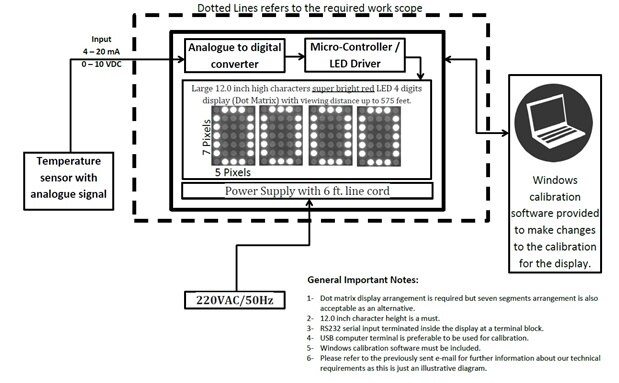
    image

    Hello i am interested in making LED Display ( DOT Matrix or 7-Segment )  for Temperature monitoring application .

    · Large 12.0 inch high characters using Indoor Red LEDS in a 5 x 7 pixel configuration; 4 digits per display. X X X X format

    · Viewing distance up to 550 - 575 feet.

    · Input will be a 4 – 20 ma signal. Output range to be defined by customer.

    · The Analog to Digital converter will be mounted inside the display enclosure. Two signal wires are used for the customers input signal.

    · Windows Calibration software provided to make changes to the calibration for the display.

    • RS232 serial input terminated inside the display at a terminal block.

    · Wall Mount tabs provided located on top of the display for mounting.

    · Approximate Dimensions: 54”L x 18”H x 2.5”D

    LED Intensity:  MCD High-Intensity Digits/Discrete LEDS

    · NEMA 1 extruded aluminum enclosure w/ red acrylic face

    POWER REQUIREMENTS: 220 VAC / 50 HZ ; 6 ft. line cord should provided


    Could you help me with the required components list .need

    • Cancel
    • Vote Up 0 Vote Down
    • Sign in to reply
    • Verify Answer
    • Cancel
  • balearicdynamics
    0 balearicdynamics over 9 years ago

    Hi tim,

    this maybe useful. Let me know, if needed I will publish a blog post or start a discussion about the details.


    https://www.tindie.com/products/alicemirror/7-segments-led-display-arduino-kit/


    Enrico

    • Cancel
    • Vote Up 0 Vote Down
    • Sign in to reply
    • Verify Answer
    • Cancel
<
element14 Community

element14 is the first online community specifically for engineers. Connect with your peers and get expert answers to your questions.

  • Members
  • Learn
  • Technologies
  • Challenges & Projects
  • Products
  • Store
  • About Us
  • Feedback & Support
  • FAQs
  • Terms of Use
  • Privacy Policy
  • Legal and Copyright Notices
  • Sitemap
  • Cookies

An Avnet Company © 2025 Premier Farnell Limited. All Rights Reserved.

Premier Farnell Ltd, registered in England and Wales (no 00876412), registered office: Farnell House, Forge Lane, Leeds LS12 2NE.

ICP 备案号 10220084.

Follow element14

  • X
  • Facebook
  • linkedin
  • YouTube