element14 Community
element14 Community
    Register Log In
  • Site
  • Search
  • Log In Register
  • Members
    Members
    • Benefits of Membership
    • Achievement Levels
    • Members Area
    • Personal Blogs
    • Feedback and Support
    • What's New on element14
  • Learn
    Learn
    • Learning Center
    • eBooks
    • STEM Academy
    • Webinars, Training and Events
    • Learning Groups
  • Technologies
    Technologies
    • 3D Printing
    • FPGA
    • Industrial Automation
    • Internet of Things
    • Power & Energy
    • Sensors
    • Technology Groups
  • Challenges & Projects
    Challenges & Projects
    • Design Challenges
    • element14 presents
    • Project14
    • Arduino Projects
    • Raspberry Pi Projects
    • Project Groups
  • Products
    Products
    • Arduino
    • Dev Tools
    • Manufacturers
    • Raspberry Pi
    • RoadTests & Reviews
    • Avnet Boards Community
    • Product Groups
  • Store
    Store
    • Visit Your Store
    • Choose Another Store
      • Europe
      •  Austria (German)
      •  Belgium (Dutch, French)
      •  Bulgaria (Bulgarian)
      •  Czech Republic (Czech)
      •  Denmark (Danish)
      •  Estonia (Estonian)
      •  Finland (Finnish)
      •  France (French)
      •  Germany (German)
      •  Hungary (Hungarian)
      •  Ireland
      •  Israel
      •  Italy (Italian)
      •  Latvia (Latvian)
      •  
      •  Lithuania (Lithuanian)
      •  Netherlands (Dutch)
      •  Norway (Norwegian)
      •  Poland (Polish)
      •  Portugal (Portuguese)
      •  Romania (Romanian)
      •  Russia (Russian)
      •  Slovakia (Slovak)
      •  Slovenia (Slovenian)
      •  Spain (Spanish)
      •  Sweden (Swedish)
      •  Switzerland(German, French)
      •  Turkey (Turkish)
      •  United Kingdom
      • Asia Pacific
      •  Australia
      •  China
      •  Hong Kong
      •  India
      •  Korea (Korean)
      •  Malaysia
      •  New Zealand
      •  Philippines
      •  Singapore
      •  Taiwan
      •  Thailand (Thai)
      • Americas
      •  Brazil (Portuguese)
      •  Canada
      •  Mexico (Spanish)
      •  United States
      Can't find the country/region you're looking for? Visit our export site or find a local distributor.
  • Translate
  • Profile
Sensors
  • Technologies
  • More
Sensors
Blog Pulse Induction Metal Detector Circuit
  • Blog
  • Forum
  • Documents
  • Events
  • Polls
  • Members
  • Mentions
  • Sub-Groups
  • Tags
  • More
  • Cancel
  • New
Sensors requires membership for participation - click to join
Blog Post Actions
  • Subscribe by email
  • More
  • Cancel
  • Share
  • Subscribe by email
  • More
  • Cancel
Group Actions
  • Group RSS
  • More
  • Cancel
Engagement
  • Author Author: dougw
  • Date Created: 28 Oct 2017 2:14 AM Date Created
  • Views 6188 views
  • Likes 4 likes
  • Comments 4 comments
  • pi metal detector
  • coin detector
  • metal detecting
  • metal detector
  • doug wong
  • metal detection circuit
  • pulse induction metal detector
Related
Recommended

Pulse Induction Metal Detector Circuit

dougw
dougw
28 Oct 2017

This blog provides a brief explanation of how pulse induction circuits detect metal objects.

Pulse induction metal detection relies on the fact that when metal is in a changing magnetic field, eddy currents are induced in the metal. These eddy currents form complete circuits which are equivalent to electro-magnets which generate their own magnetic fields. As these induced magnetic fields fluctuate, they also induce current in the originating inductor (antenna).

If the antenna in this circuit is driven with a current pulse, when the pulse ends, current will continue to flow in the antenna (inductor) and in this case the current will decay because there is a resistive load on the antenna. As the current decays, the magnetic field will also collapse.

The effect of foreign metal in the magnetic field of the antenna and the resulting fields produced by induced eddy currents is to prolong the decay of the current in the antenna. We can detect metal near the antenna by noticing when the decay period starts to extend.


This is an image of the PCB discussed in the videos:

image

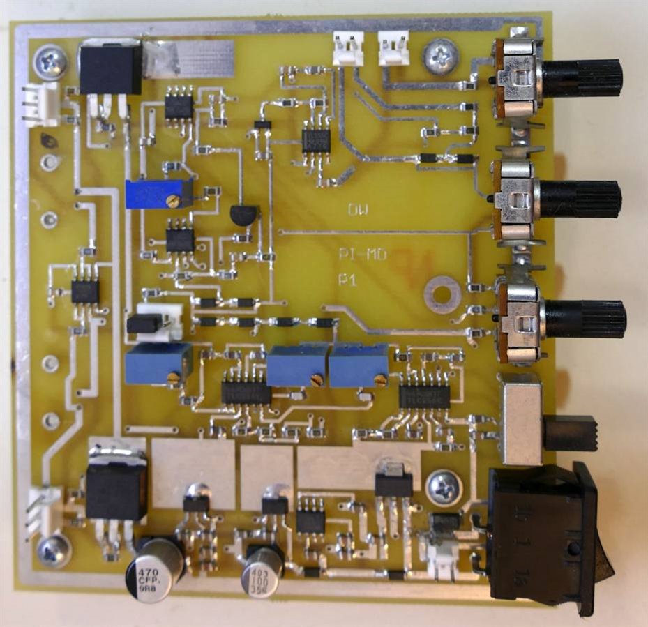
  • The circuitry along the bottom is all power supply circuitry
  • The 14 pin chips and blue pots  above the power supply are 556 timers controlling all the timing
  • The connectors at the left are outputs to inductive antennas
  • The big power transistors at the left - top and bottom are driving the antennas
  • The control pots at the right adjust threshold, ammeter scaling and volume
  • The connectors at the top are for a needle meter and a piezo buzzer

Here is a video showing how this circuit performs this function:

You don't have permission to edit metadata of this video.
Edit media
x
image
Upload Preview
image


Here is a video showing how the circuit responds to various coins from around the world:

You don't have permission to edit metadata of this video.
Edit media
x
image
Upload Preview
image


I originally designed this circuit board to experiment with pulse induction metal detection and learn more about it.

The project has been a great way to delve into the subject.

At some point I will convert this circuit to a microcontroller with LCD display (and shrink the board at the same time) and post a blog about it.

  • Sign in to reply

Top Comments

  • jw0752
    jw0752 over 5 years ago +2
    Hi Doug, That is a nice looking circuit setup. When I used to service for the Radio Shack they sold a cheap metal locator. That unit had 2 oscillators that beat against each other to produce a tone. One…
  • dougw
    dougw over 5 years ago in reply to jw0752 +1
    The circuit has helped me learn more about the topic, so naturally I would design it differently today.
  • ninjatrent
    ninjatrent over 5 years ago +1
    Great post. Interesting content.
  • techinnovation4u
    techinnovation4u over 4 years ago

    Hello Sir,

    i really like your Project.

    Appreciate it.


    I want this for my final year universality project.

    please contact me

    techinnovation4u@gmail.com

    • Cancel
    • Vote Up +1 Vote Down
    • Sign in to reply
    • More
    • Cancel
  • ninjatrent
    ninjatrent over 5 years ago

    Great post. Interesting content.

    • Cancel
    • Vote Up +1 Vote Down
    • Sign in to reply
    • More
    • Cancel
  • dougw
    dougw over 5 years ago in reply to jw0752

    The circuit has helped me learn more about the topic, so naturally I would design it differently today.

    • Cancel
    • Vote Up +1 Vote Down
    • Sign in to reply
    • More
    • Cancel
  • jw0752
    jw0752 over 5 years ago

    Hi Doug,


    That is a nice looking circuit setup. When I used to service for the Radio Shack they sold a cheap metal locator. That unit had 2 oscillators that beat against each other to produce a tone. One oscillator had the detector coil as part of its oscillator. If metal came near the external detector coil the inductance would change and the beat frequency would change. It was a simple but effective approach. I am sure the technology has improved since the late 1970s.


    John

    • Cancel
    • Vote Up +2 Vote Down
    • Sign in to reply
    • More
    • Cancel
element14 Community

element14 is the first online community specifically for engineers. Connect with your peers and get expert answers to your questions.

  • Members
  • Learn
  • Technologies
  • Challenges & Projects
  • Products
  • Store
  • About Us
  • Feedback & Support
  • FAQs
  • Terms of Use
  • Privacy Policy
  • Legal and Copyright Notices
  • Sitemap
  • Cookies

An Avnet Company © 2023 Premier Farnell Limited. All Rights Reserved.

Premier Farnell Ltd, registered in England and Wales (no 00876412), registered office: Farnell House, Forge Lane, Leeds LS12 2NE.

ICP 备案号 10220084.

Follow element14

  • Facebook
  • Twitter
  • linkedin
  • YouTube