|
I was Road Testing the Rohm SensorShield-EVK-003 (Arduino Compatible) and the sensors that come with it, in 2017.
|
The Heart Monitor Sensor
The BH1790GLC sensor uses visible light (green) to measure heart rate metrics.
Two green LEDs, best placed right next to the sensor and shining up, are pulsed by the IC's LED driver. Pulsing and intensity are configurable. There is a link with the sensor's sampling rate.
You put your fingertip on top of the LEDs and sensor.
The sensor has an IR-block and green-pass filter, and measures the light of the LEDs that passed through your finger (and blood vessels).
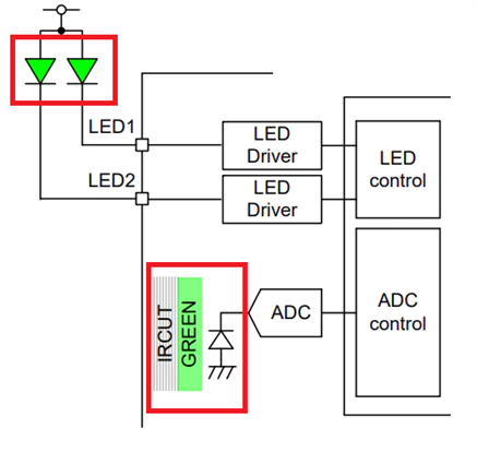

image source: annotated from BH1790GLC datasheet and evaluation board landing page
This footprint, with SMD LEDs, is tiny. If you'd build this into a housing, a green-friendly protection filter can be used to protect the hardware. Touch detection works with and without a filter on top.
There are 3 power supplies. One for the IC proper. A second for the i2c I/O. The two external LEDs need their own supply.
Evaluation Board and Circuit
The evaluation board circuit is an exact implementation of the datasheet design.
Just visible in the right lower corner on the PCB Bottom photo is the external LED power supply wire .
The board uses a 3V VCC. The LEDs need 5V, and there's a dedicated wire for that
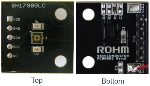
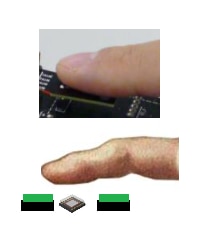
image source: evaluation board user's manual and evaluation board user's manual, finger by Leonardo Da Vinci (fair use)
The BH1790 uses the i2c protocol. It supports speeds up to 400 kHz.
The application circuit shows the i2c pull-up resistors. Although the evaluation module has a footprint for them, they aren't populated.
On the evaluation module, VCC2 is connected to VCC1 via a 0R resistor.
The i2c pull-up circuit is part of Rohm's evaluation base shield.
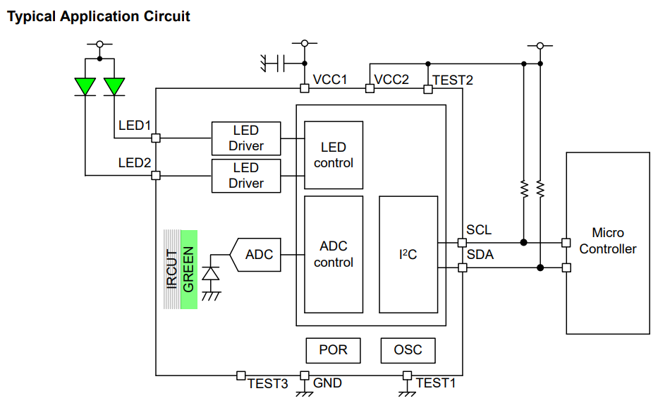
image of the typical circuit for this sensor. source: BH1790GLC datasheet
The schematic of the evaluation board is shown below. As indicated, VCC2 is tied to VCC1/VDD. i2c components are not populated because they are provided on the base shield.

image of the actual evaluation board circuit. source: evaluation board landing page
Software and Firmware
There are two examples, available as ZIP from the product home page.
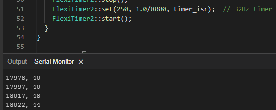
A simple example (BH1790GLC.zip) initialises the IC with default values, then reads and displays sensor raw data, on a 32 Hz sample rate.
The two data values are the raw sensor measurement with LED ON and OFF.
It just relies on Rohm's IC wrapper, and the Arduino FlexiTimer2 library to request the samples.
This is the minimum setup to get samples out of the sensor.
A more elaborate example (BH1790GLC_HeartRate.zip) returns the measured heart rate. This one uses a 32 step pulse wave - and the pulse wave sensor (at the same 32 Hz sample frequency).
It uses the same 2 libraries as the first one, but then additional APIs from Rohm for the more complex averaging and pulse train control:
- hr_bh1790: provides a heartrate API
- pw_bh1790: Pulse Wave Sensor API
- pwCalc: Pulse Wave Calculation API
- touchDet: Touch Detection API
- lxCtrl: LED control API
- iirFilter: infinite impulse response filter API
- movingAverage: Moving Average API
Although the sketch for this elaborate example is simple, there is a lot happening in the background:
- When there's no finger on the sensor, the LEDs are off.
- samples are validated
- pulse wave is used
- pulse data is filtered by the software DSP infinite impulse response filter
- data is averaged over 32 samples.
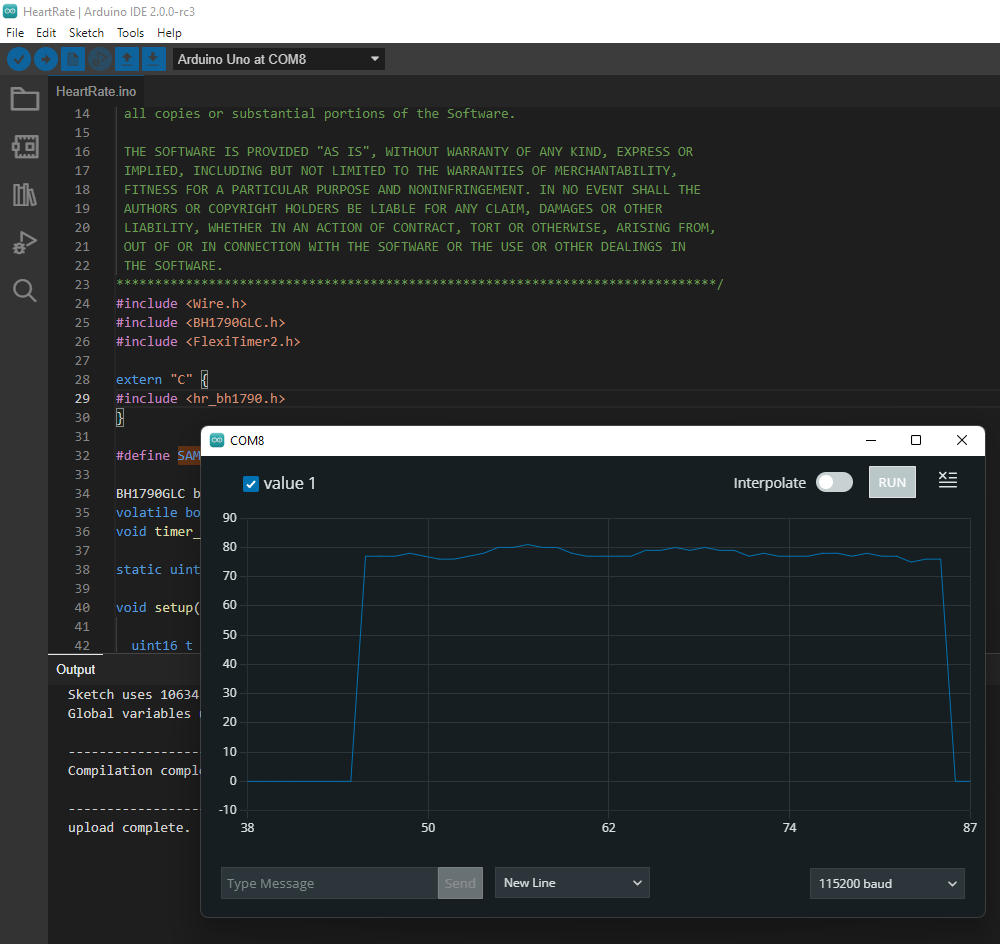
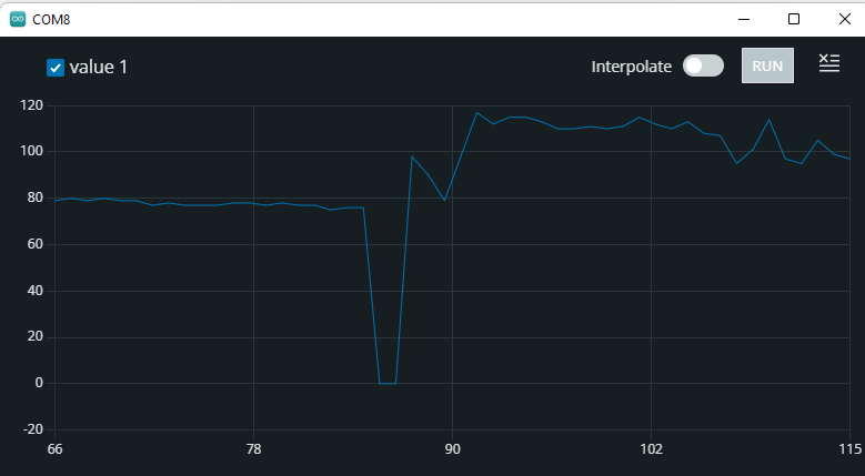
Here's me at ease, then I paused the sampling and ran down and up all the stairs of my house. Then continued sampling:
As a follow-up, I'll solder wires to the two LEDs and probe them with an oscilloscope. For the simple and elaborate example. I'll post the findings in the comments.


