element14 Community
element14 Community
    Register Log In
  • Site
  • Search
  • Log In Register
  • Community Hub
    Community Hub
    • What's New on element14
    • Feedback and Support
    • Benefits of Membership
    • Personal Blogs
    • Members Area
    • Achievement Levels
  • Learn
    Learn
    • Ask an Expert
    • eBooks
    • element14 presents
    • Learning Center
    • Tech Spotlight
    • STEM Academy
    • Webinars, Training and Events
    • Learning Groups
  • Technologies
    Technologies
    • 3D Printing
    • FPGA
    • Industrial Automation
    • Internet of Things
    • Power & Energy
    • Sensors
    • Technology Groups
  • Challenges & Projects
    Challenges & Projects
    • Design Challenges
    • element14 presents Projects
    • Project14
    • Arduino Projects
    • Raspberry Pi Projects
    • Project Groups
  • Products
    Products
    • Arduino
    • Avnet & Tria Boards Community
    • Dev Tools
    • Manufacturers
    • Multicomp Pro
    • Product Groups
    • Raspberry Pi
    • RoadTests & Reviews
  • About Us
  • Store
    Store
    • Visit Your Store
    • Choose another store...
      • Europe
      •  Austria (German)
      •  Belgium (Dutch, French)
      •  Bulgaria (Bulgarian)
      •  Czech Republic (Czech)
      •  Denmark (Danish)
      •  Estonia (Estonian)
      •  Finland (Finnish)
      •  France (French)
      •  Germany (German)
      •  Hungary (Hungarian)
      •  Ireland
      •  Israel
      •  Italy (Italian)
      •  Latvia (Latvian)
      •  
      •  Lithuania (Lithuanian)
      •  Netherlands (Dutch)
      •  Norway (Norwegian)
      •  Poland (Polish)
      •  Portugal (Portuguese)
      •  Romania (Romanian)
      •  Russia (Russian)
      •  Slovakia (Slovak)
      •  Slovenia (Slovenian)
      •  Spain (Spanish)
      •  Sweden (Swedish)
      •  Switzerland(German, French)
      •  Turkey (Turkish)
      •  United Kingdom
      • Asia Pacific
      •  Australia
      •  China
      •  Hong Kong
      •  India
      •  Korea (Korean)
      •  Malaysia
      •  New Zealand
      •  Philippines
      •  Singapore
      •  Taiwan
      •  Thailand (Thai)
      • Americas
      •  Brazil (Portuguese)
      •  Canada
      •  Mexico (Spanish)
      •  United States
      Can't find the country/region you're looking for? Visit our export site or find a local distributor.
  • Translate
  • Profile
  • Settings
Sensors
  • Technologies
  • More
Sensors
Sensor Forum how to find resolution of capacitative sensors?
  • Blog
  • Forum
  • Documents
  • Quiz
  • Events
  • Polls
  • Members
  • Mentions
  • Sub-Groups
  • Tags
  • More
  • Cancel
  • New
Join Sensors to participate - click to join for free!
Actions
  • Share
  • More
  • Cancel
Forum Thread Details
  • State Not Answered
  • Replies 6 replies
  • Subscribers 342 subscribers
  • Views 1399 views
  • Users 0 members are here
Related

how to find resolution of capacitative sensors?

Former Member
Former Member over 10 years ago

hi

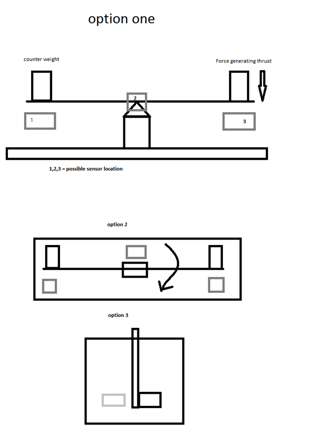
i am looking to make a non contact or contact based position sensor to use as way to measure force in mN scale.

i am totally new to this field, and looking for suggestions about sensor selection. And most importantly, How do i know resolution of each sensor ? it is not given in tech files.

  • Sign in to reply
  • Cancel

Top Replies

  • michaelkellett
    michaelkellett over 10 years ago +1
    I think you've posted a similar question elsewhere. As I said in reply to your other post you need to describe your problem in much more detail to get good answers Capacitive sensors can have infinite…
Parents
  • michaelkellett
    0 michaelkellett over 10 years ago

    I think you've posted  a similar question elsewhere.


    As I said in reply to your other post you need to describe your problem in much more detail to get good answers


    Capacitive sensors can have infinite resolution  - the limits on resolution will be determined by the measuring electronics.

    The simplest way to make a force sensor is by using strain gauges.

    Google for 'Load cells' and ' force sensors'


    If you want to make your own then bonded metal strain gauge is often the best route.


    Google 'Vishay strain gauges'


    If you can describe your problem in a lot more detail it will be possible to help you more.


    MK


    .

    • Cancel
    • Vote Up +1 Vote Down
    • Sign in to reply
    • Verify Answer
    • Cancel
  • Former Member
    0 Former Member over 10 years ago in reply to michaelkellett

    hi,

    in the attached sketch , you can see what i am trying to do. Load cells with such high sensitivity and resolution upto 0.1mg are very expensive. and often unsuitable unless an even expensive rig is prepared for them. plus, there are many constrains that will effect the results.

    in this sketch, 1,2,3, and grey boxes are showing possible location for sensor placement.


    For measurement of thrust, What i am planning to do is to first measure displacement in the rig by placing known weights as simulated force. i.e. 1g, 0.5g etc. and plot a graph of displacement in mm or micro meter vs. force applied. and with this calibration graph, I will be able to measure thrust in mN range. Right now, I have not selected build material for rig, because what i have read in these forums is that, build material should be according to type of sensor.

    From development kits, I have found is:

    TEXAS INSTRUMENTS  LDC1000EVM  LDC1000, INDUCTIVE SENSING, EVAL BOARD

    http://my.element14.com/texas-instruments/ldc1000evm/ldc1000-inductive-sensing-eval/dp/2360423


    I think it may work in my case, but i wasnt sure about sensitivity and resolution of sensors installed in this module. And also, Is there any other sensor or accessory  I may have purchase to make this module work ?


    Other option I have is to use graphtec GL220 data logger with a sensor, but i am not sure if it will work directly with DAQ or not. My friend told me that i may have to build a controller unit to use properly.

    In short, according to your experience, can you confirm if this module would work or not. and do I need additional components ?

    out of 3 options for rig setup, which one you think will be best option.


    image

    • Cancel
    • Vote Up 0 Vote Down
    • Sign in to reply
    • Verify Answer
    • Cancel
  • michaelkellett
    0 michaelkellett over 10 years ago in reply to Former Member

    There is still nothing like enough detail in your description:


    How far can the sensing point move when the force is applied

    What is applying the force

    What resolution, accuracy, repeatability and hysteresis are acceptable

    How fast must the sensor respond.


    Open loop inductive will be awful for most of these, forget the LDC1000EVM  - it just isn't the way forward here.

    Ready made load cells are much cheaper than a lot of precision engineering unless you count machine shop time as free.

    Look at LOAD CELLS > Platform Load Cell 1004 this is a suitable (possibly) part - there are many others on offer.

    If you are determined on  a DIY sensor then at least consider force balance (Google it)  (may not work for you but you don't explain enough to tell).

    If long term stability is not important then making your own load cell is not too hard.


    MK

    • Cancel
    • Vote Up 0 Vote Down
    • Sign in to reply
    • Verify Answer
    • Cancel
  • Former Member
    0 Former Member over 10 years ago in reply to michaelkellett

    How far can the sensing point move when the force is applied

    less than 1mm.  resolution of 1~10micron will be required.


    What is applying the force

    a MEMS based micro thruster, (micro rocket)


    What resolution, accuracy, repeatability and hysteresis are acceptable

    +-100 micro newton will be ideal. in terms of weight, 0.1mg will be okay.

    repeatability within +-3~5% will be okay.


    How fast must the sensor respond.

    anything above 100Hz(100 samples per second) will be good.


    but sadly in my case, budget is below 200USD, so i am trying to find alternate sensors which could do the job.


    here is the attached diagram of original rig, which i am reproduce.


    image

    Original text "


    Thrust measurement

    A torsional thrust stand that resolves forces in the order of

    micronewton was constructed in our center. This dedicated

    thrust measurement facility was set up not only to evaluate

    the performance of VLM but also for other micropropulsion

    systems, e.g. a pulsed plasma thruster. A block diagram of

    the actual setup is illustrated in figure 5. A detailed working

    principle of a torsional thrust stand can be found elsewhere

    [26, 27]. In general, our thrust stand consists of an aluminum

    alloy beam of 60

    cm long supported by a flexural pivot

    (6012–400, Riverhawk) which provides the restoring force.

    Beam deflection due to the VLM operation was measured

    using a high precision optical linear displacement sensor

    (ILD 2300–2, MicroEpsilon) which has a resolution of 0.03μm at 20

    kHz measuring rate. An electrostatic calibrator

    was used to generate consistent and repeatable calibration

    force in order to establish the relationship between beam

    deflection and force. The entire setup was covered by a

    plexiglass protective box to reduce disturbances due to the

    external environment.

    Direct measurement of force from the VLM using the thrust

    stand is difficult. Mounting of the liquid feedline on the thrust

    stand surface has limited the thrust stand resolution [

    13].

    Alternatively, an indirect measurement technique was used.

    A heater pad was installed on the thrust stand and heated to a

    temperature of approximately 60

    °C. The VLM was externally

    mounted and aligned so that the vapor jets would impinge on

    the surface of the heater pad. The heated surface prevented the

    condensation of water vapor. The deflection of the thrust stand

    due to the vapor jet impingement was recorded. The same

    syringe pump and power supply were used for the operation

    of VLM.".

    • Cancel
    • Vote Up 0 Vote Down
    • Sign in to reply
    • Verify Answer
    • Cancel
Reply
  • Former Member
    0 Former Member over 10 years ago in reply to michaelkellett

    How far can the sensing point move when the force is applied

    less than 1mm.  resolution of 1~10micron will be required.


    What is applying the force

    a MEMS based micro thruster, (micro rocket)


    What resolution, accuracy, repeatability and hysteresis are acceptable

    +-100 micro newton will be ideal. in terms of weight, 0.1mg will be okay.

    repeatability within +-3~5% will be okay.


    How fast must the sensor respond.

    anything above 100Hz(100 samples per second) will be good.


    but sadly in my case, budget is below 200USD, so i am trying to find alternate sensors which could do the job.


    here is the attached diagram of original rig, which i am reproduce.


    image

    Original text "


    Thrust measurement

    A torsional thrust stand that resolves forces in the order of

    micronewton was constructed in our center. This dedicated

    thrust measurement facility was set up not only to evaluate

    the performance of VLM but also for other micropropulsion

    systems, e.g. a pulsed plasma thruster. A block diagram of

    the actual setup is illustrated in figure 5. A detailed working

    principle of a torsional thrust stand can be found elsewhere

    [26, 27]. In general, our thrust stand consists of an aluminum

    alloy beam of 60

    cm long supported by a flexural pivot

    (6012–400, Riverhawk) which provides the restoring force.

    Beam deflection due to the VLM operation was measured

    using a high precision optical linear displacement sensor

    (ILD 2300–2, MicroEpsilon) which has a resolution of 0.03μm at 20

    kHz measuring rate. An electrostatic calibrator

    was used to generate consistent and repeatable calibration

    force in order to establish the relationship between beam

    deflection and force. The entire setup was covered by a

    plexiglass protective box to reduce disturbances due to the

    external environment.

    Direct measurement of force from the VLM using the thrust

    stand is difficult. Mounting of the liquid feedline on the thrust

    stand surface has limited the thrust stand resolution [

    13].

    Alternatively, an indirect measurement technique was used.

    A heater pad was installed on the thrust stand and heated to a

    temperature of approximately 60

    °C. The VLM was externally

    mounted and aligned so that the vapor jets would impinge on

    the surface of the heater pad. The heated surface prevented the

    condensation of water vapor. The deflection of the thrust stand

    due to the vapor jet impingement was recorded. The same

    syringe pump and power supply were used for the operation

    of VLM.".

    • Cancel
    • Vote Up 0 Vote Down
    • Sign in to reply
    • Verify Answer
    • Cancel
Children
  • Former Member
    0 Former Member over 10 years ago in reply to Former Member

    http://mae.eng.uci.edu/Faculty/MGC/Articles/MGC_RevSciInstrum_03.pdf


    for more details

    • Cancel
    • Vote Up 0 Vote Down
    • Sign in to reply
    • Verify Answer
    • Cancel
  • michaelkellett
    0 michaelkellett over 10 years ago in reply to Former Member

    I think your best bet, taking into account the budget, is a capacitive sensor. Use flat plates with an area of at least 10cm^2 and you should get a reasonable capacity (9pF at 1mm separation). Make an oscillator where the frequency of oscillation is determined by C (single op-amp astable sounds right) and use  a micro to measure the frequency.  Design it to go at 100kHz at 1mm separation and it will rise to 200kHz at 2mm separation (f proportional to 1/distance).

    You can get 1 part in 1000 resolution and 100 readings per second.


    It won't be as easy as this sounds - you need the plates to stay // as they move and stray capacitance effects will cause problems. Put the oscillator right next to the fixed plate so you don't have long wires.


    I've designed quite a few transducers in my time but I don't know how much experience you have had - but expect it take a few weeks to get this working right.


    MK

    • Cancel
    • Vote Up 0 Vote Down
    • Sign in to reply
    • Verify Answer
    • Cancel
element14 Community

element14 is the first online community specifically for engineers. Connect with your peers and get expert answers to your questions.

  • Members
  • Learn
  • Technologies
  • Challenges & Projects
  • Products
  • Store
  • About Us
  • Feedback & Support
  • FAQs
  • Terms of Use
  • Privacy Policy
  • Legal and Copyright Notices
  • Sitemap
  • Cookies

An Avnet Company © 2025 Premier Farnell Limited. All Rights Reserved.

Premier Farnell Ltd, registered in England and Wales (no 00876412), registered office: Farnell House, Forge Lane, Leeds LS12 2NE.

ICP 备案号 10220084.

Follow element14

  • X
  • Facebook
  • linkedin
  • YouTube