element14 Community
element14 Community
    Register Log In
  • Site
  • Search
  • Log In Register
  • About Us
  • Community Hub
    Community Hub
    • What's New on element14
    • Feedback and Support
    • Benefits of Membership
    • Personal Blogs
    • Members Area
    • Achievement Levels
  • Learn
    Learn
    • Ask an Expert
    • eBooks
    • element14 presents
    • Learning Center
    • Tech Spotlight
    • STEM Academy
    • Webinars, Training and Events
    • Learning Groups
  • Technologies
    Technologies
    • 3D Printing
    • FPGA
    • Industrial Automation
    • Internet of Things
    • Power & Energy
    • Sensors
    • Technology Groups
  • Challenges & Projects
    Challenges & Projects
    • Design Challenges
    • element14 presents Projects
    • Project14
    • Arduino Projects
    • Raspberry Pi Projects
    • Project Groups
  • Products
    Products
    • Arduino
    • Avnet Boards Community
    • Dev Tools
    • Manufacturers
    • Multicomp Pro
    • Product Groups
    • Raspberry Pi
    • RoadTests & Reviews
  • Store
    Store
    • Visit Your Store
    • Choose another store...
      • Europe
      •  Austria (German)
      •  Belgium (Dutch, French)
      •  Bulgaria (Bulgarian)
      •  Czech Republic (Czech)
      •  Denmark (Danish)
      •  Estonia (Estonian)
      •  Finland (Finnish)
      •  France (French)
      •  Germany (German)
      •  Hungary (Hungarian)
      •  Ireland
      •  Israel
      •  Italy (Italian)
      •  Latvia (Latvian)
      •  
      •  Lithuania (Lithuanian)
      •  Netherlands (Dutch)
      •  Norway (Norwegian)
      •  Poland (Polish)
      •  Portugal (Portuguese)
      •  Romania (Romanian)
      •  Russia (Russian)
      •  Slovakia (Slovak)
      •  Slovenia (Slovenian)
      •  Spain (Spanish)
      •  Sweden (Swedish)
      •  Switzerland(German, French)
      •  Turkey (Turkish)
      •  United Kingdom
      • Asia Pacific
      •  Australia
      •  China
      •  Hong Kong
      •  India
      •  Korea (Korean)
      •  Malaysia
      •  New Zealand
      •  Philippines
      •  Singapore
      •  Taiwan
      •  Thailand (Thai)
      • Americas
      •  Brazil (Portuguese)
      •  Canada
      •  Mexico (Spanish)
      •  United States
      Can't find the country/region you're looking for? Visit our export site or find a local distributor.
  • Translate
  • Profile
  • Settings
Sensors
  • Technologies
  • More
Sensors
Sensor Forum Any ideas for low-cost Thermocouple Interfacing methods?
  • Blog
  • Forum
  • Documents
  • Quiz
  • Events
  • Polls
  • Members
  • Mentions
  • Sub-Groups
  • Tags
  • More
  • Cancel
  • New
Join Sensors to participate - click to join for free!
Actions
  • Share
  • More
  • Cancel
Forum Thread Details
  • Replies 25 replies
  • Subscribers 340 subscribers
  • Views 6476 views
  • Users 0 members are here
  • thermocouple
  • thermistor
Related

Any ideas for low-cost Thermocouple Interfacing methods?

shabaz
shabaz over 3 years ago

Note: See here for a project that resulted from this discussion: BLE EasyTempProbe 

Hi,

Since thermocouple measurement ICs are getting expensive/hard to find, I wished to use a single channel ADC, for thermocouple measurements (actually, I want to use a dual channel ADC for two thermocouples, but it's likely the same problem just doubled!).

The trouble is, the cold end of the thermocouple needs measuring too, and I was thinking of using a thermistor for that because that's easier to obtain (and cheaper) than an IC sensor. In summary, I wished to multiplex a thermistor and a thermocouple.

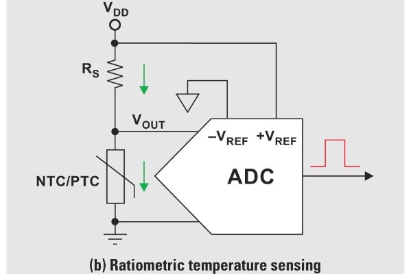
I've come up with the diagram below so far and wish to use it in an environment where the cold junction might be in the range of -40 to +50 deg C, and the thermocouple might be in the range of -40 to +400 deg C (maybe a Type J thermocouple). I think it will have an error of a few deg C. The ADC is 16-bit, and I likely won't be using the whole range of it. The ADC has a PGA of up to 8X, so it will be set to 8X when measuring the thermocouple.

The main benefit of the proposal below is that it is cheap since it just needs a couple of transistors and a few resistors. I could think of more complex circuits for a more accurate measurement, but it would be nice to see if this is good enough, or if it could be tweaked to be good enough unless anyone has other suggestions.

If it works, this would be a cheap way (under $5, ADC included) to have two thermocouples each with their own compensation, with the drawbacks that accuracy might be a few degrees at best, and no isolation either, unfortunately. 

Any ideas would be gratefully appreciated, since I'm sure I may be missing some great techniques, missing the wood for the trees, etc! Has anyone come across any low-cost methods to do such a thing? Any mistakes I'm making?

image

  • Sign in to reply
  • Cancel

Top Replies

  • michaelkellett
    michaelkellett over 3 years ago +6
    Thinking out loud: Both transistors off, no path on input to 0V so ADC pins 2 and 3 pulled to 3.3V, probably outsiede ADC common mode range. Both transistors on, both sides of thermocouple pulled to…
  • shabaz
    shabaz over 3 years ago +3
    Hi fmilburn (Replying here to remove the comment indent, since I wanted to share some diagrams) I've had a shot at doing it, and was close to giving up since I was seeing huge errors!, but it was…
  • shabaz
    shabaz over 3 years ago +3
    I had a short bit of time to try to prototype this, it is not tested yet. The jumper positions on the left select different resistors, to simulate the thermistor, to be at a temperature of -30, 0, 25 or…
Parents
  • shabaz
    shabaz over 3 years ago

    Hi fmilburn

    (Replying here to remove the comment indent, since I wanted to share some diagrams)

    I've had a shot at doing it, and was close to giving up since I was seeing huge errors!, but it was a mistake in a calculation. I think it's looking good, but reality might be different!

    Referring to this circuit (it is similar to before, except I've reduced the filter resistance further), I first closed the switch and tried seeing what the expected values should be. The switch closed is when the thermistor (cold junction) temperature needs to be measured:

    image

    I picked a NTC thermistor with 1 kohm resistance at 25 deg C, and used a Beta value of 3650. In the screenshot below, the Excel spreadheet boxed section labeled "Standalone Thermistor" was used to check that the formula was working for conversions from resistance to temperature, and vice-versa. Green cells are input values, pink cells are outputs from formulas.

    The spreadsheet is very clunky, it isn't all automated, some values are currently looked up.

    Using the normal potential divider formula (i.e. Ohms law) I worked out what the voltage across the thermistor would be, and that is in the box labelled "Thermistor in Potential Divider".

    Once I had this, I used a Spice simulation to see what it thought I would get, with the switch closed. The "Thermistor error" box is the area where I tried simulating from -30 to +50 degrees C, which is likely to be the max range that the cold junction will encounter.

    I varied the thermistor voltage between the limits of -5mV and +20mV since that will cover more than 400 degrees C of interest area, and the thermocouple voltage will have a slight impact when reading the thermistor voltage. It turns out, the error is small, mostly smaller than 1 deg C apart from at the 50 deg C extreme. The green cells at the right side of the "Thermistor error" box show the Spice simulation results, and I'm really happy with those. The thermistor measurement looks good with the current layout.

    image

    Next, I moved to the thermocouple measurements, i.e. with the switch open. I didn't use a formula, I just used a lookup table from a datasheet for a Type-K thermocouple. It was a similar idea to the thermistor, i.e. just trying to model in Excel what is expected, and comparing with Spice. In the case of the thermocouple, since the measurement of that includes the thermistor resistance, the circuit looks like a potential divider circuit where the source voltage is the thermocouple voltage (Vthermocouple), and the resistors in the potential divider are R2, RADC1, and the thermistor. Taking them into account, I can work out what the voltage across the ADC should be (Vadc), and vice-versa, i.e. with a given Vadc measurement, to convert back from that to determine what Vthermocouple is. 

    I used the "Vadc for Thermocouple measurements" boxed section for this, while varying the thermistor resistance across the range -30 degC to 50 deg C, for thermocouple voltages of -5mV and +20mV, which correspond to -154 degC and 485 degC if the cold junction were at 0 degC.

    The Spice simulation agrees very closely, so this is good confidence that the formulas are now good, and that if this circuit was built, then it may work!

    The one major caveat is, that the resistances in series with the thermocouple will cause huge error, if the ADC internal resistance changes. because that ADC resistance is part of the potential divider. The spice simulation may be useless, because of this assumption (I don't have a spice model of an ADC, I just modeled using the resistance in the datasheet, which is 2.25 Mohm divided by the gain, which will likely need to be set to the maximum which is 8). Thats 280 kohm, although I used a value of 250 kohm, the concept is the same, I would just need to change that param in the spreadsheet.

    I can reduce the effect of the ADC input, by reducing the value of the thermistor, so I've chosen a small value of 1 kohm at 25 deg C, and perhaps reduce further by paralleling it with another resistor, although that may be unnecessary. I don't know though, it's probably time to try the circuit out for real! 

    It will be possible to test the performance by applying a voltage in place of the thermocouple, this will simulate any temperature, and using a worst-case resistance for the thermistor, which would be at the coldest temperature, e.g. 15.94kohm for -30 deg C. 

    If that RADC1 value doesn't change much, then the measurement might be good. From the simulation, a 10% change in the value of RADC1 barely makes a difference to the measurement, so that's a good sign I guess, but I really don't know in practice if it will change even more. 

    In summary, there are positive signs, but it could all go wrong in practice.

    • Cancel
    • Vote Up +3 Vote Down
    • Sign in to reply
    • Cancel
  • geralds
    geralds over 3 years ago in reply to shabaz

    High shabaz.

    You mentioned you will use the MCP3426 ADC.

    Please just read this manual: -> The MCP has implemented a PGA before the ADC, and has a MUX before the PGA.

    https://ww1.microchip.com/downloads/en/DeviceDoc/22226a.pdf

    I think your circuit does not work well. Soo simple making as you like, sorry I think that does not work well.

    Just some thinking about:

    the transistors have a U_C-E resistor, so you have a C-E saturating voltage.

    So then you have no good GND or virtual GND point. And the transistor also is thermo-resistive.

    A second point: do you measure absolute or ratiometric?

    image 

    The absolute temp. sensing, the +Vref has a separate ref. voltage.

    A 4-wire sensor management:

    image 

    May be this might help, table of thermistors as well an OPAMP circuit:

    https://electronics.stackexchange.com/questions/521430/temperature-sensing-with-ads1115/521514

    But the idea is good. The first I thought was that the Q2 transistor is not needing.

    The Q1 I suggest a BSS (bipolar switch type, very low R_C-E) or MOSFET type which with you makes a GND.

    The thermistor and the thermocouple are in serial wired - > also all the resistors in this wire - then you can calculate with a summing resistor.

    A simulation software would not help really. Of the other hand - the simulation software LTSpice VII from Analog Devices can simulate ADCs, it has ADC scripts.

    The ADC-resistors in the simulation are to high.

    Its a good idea.. I look forward.

    Best Regards

    Gerald

    ---

    • Cancel
    • Vote Up +2 Vote Down
    • Sign in to reply
    • Cancel
  • shabaz
    shabaz over 3 years ago in reply to geralds

    Hi Gerald,

    Thanks for the info! The datasheet is very confusing to me, because although there is a PGA, the input circuit shows this, with no PGA  (or mux) indicated!:

    image

    I found it hard to be conclusive exactly what the IC does. I tried it just now, and I still need to record the results properly, but it is looking promising, although it's very reliant on this chip, since the input resistance will change if I use a different ADC. This is a limitation of the circuit, since there is so much resistance in the thermocouple circuit. The other limitation is that the thermocouple voltage cannot be determined without first determining the thermistor resistance in this circuit.

    What I did in the code was first to measure the thermistor, that's accurate to within 1 deg C, for the range -30 to +50 deg C, which is all I tested (I have only tested for a few minutes so far). I simulated the thermistor with fixed value resistors.

    Next, I applied -5mV to +20mV to the thermocouple input, and then used the ADC measurement in a formula that includes the thermistor measurement. By compensating like that, the voltage at the thermocouple input seems to be readable while only changing by a few tens of uV as the thermistor is varied from -30 to +50, since I am taking the thermistor measurement into account.

    To summarize, the code first reads the thermistor, then switches to read the thermocouple, and compensates for the thermistor and the ADC differential input resistance (I used 250k which is an error, just remembered I should change that to 280k in the code).

    I'll run some more tests during the day, and paste the results.

    Here is a snippet (I have not captured any more yet).

    The snippet shows a 20 mV connection to the thermocouple, and the thermistor was changed from 50 deg C to 30 deg C.

    19.96mV corresponds to 484degC (Type K), and 19.91mV is 483 degC (I have done no cold junction compensation yet so it's just a measurement of what's at the thermocouple terminals), and the error+noise isn't too bad, given I was only hoping for it to be within a few degrees C. This is with no real thermocouple or thermistor, and no voltage reference for the thermistor circuit, since the ADC has no reference voltage output pin, and I used the 3.3V regulated output from the Pi Pico (which is running the code). These results should be improvable.

    The error message in the output isn't an issue, it occurred when I moved the thermistor jumper from 50 to -30. Also, I'm averaging 10 samples for each result here.

    10: thermistor = 50.61 degC, thermocouple = 19.96 mV
    10: thermistor = 50.61 degC, thermocouple = 19.96 mV
    10: thermistor = 50.61 degC, thermocouple = 19.96 mV
    10: thermistor = 50.61 degC, thermocouple = 19.96 mV
    10: thermistor = 50.60 degC, thermocouple = 19.96 mV
    error: thermistor appears to be missing or open circuit!
    10: thermistor = -273.15 degC, thermocouple = 4.53 mV
    10: thermistor = -29.13 degC, thermocouple = 19.91 mV
    10: thermistor = -29.13 degC, thermocouple = 19.91 mV
    10: thermistor = -29.13 degC, thermocouple = 19.94 mV
    10: thermistor = -29.13 degC, thermocouple = 19.95 mV
    10: thermistor = -29.13 degC, thermocouple = 19.97 mV
    10: thermistor = -29.13 degC, thermocouple = 19.92 mV
    10: thermistor = -29.13 degC, thermocouple = 19.90 mV
    10: thermistor = -29.13 degC, thermocouple = 19.92 mV
    10: thermistor = -29.13 degC, thermocouple = 19.96 mV
    10: thermistor = -29.13 degC, thermocouple = 19.97 mV

    • Cancel
    • Vote Up +2 Vote Down
    • Sign in to reply
    • Cancel
  • jc2048
    jc2048 over 3 years ago in reply to shabaz

    That's the scheme Microchip traditionally used with their SAR converters in their microcontrollers: a capacitor sample and hold, followed by the converter itself, without a high-impedance buffer on the front end. With the small microcontroller parts, they recommended a source resistance of lower than 10k to be sure of getting the capacitor charged in the sample period, to obtain the full resolution.

    This looks like a differential version of the same scheme. My guess would be that the mux is effectively the sampling switch (both would comprise analog switches, so why not roll them into one) and the PGA goes after the sampling capacitor (it needs a buffer anyway, to hold the sample voltage for the conversion period, so why not make it the PGA).

    The datasheet does say in one section that it's best used with a low impedance source like an op-amp output, though it's all a bit sketchy on actual values for things.

    If you have a high source impedance, but keep sampling one channel that doesn't move in voltage very quickly, then the values will come out at the full resolution after a couple of samples because the capacitor is already mostly charged at the start of the sample period. Where it would be more of an issue is where the mux was switching alternately between two channels, with the capacitor voltage having to swing back and forth between the two ends of the scale, because then you'd probably start to loose some of the resolution.

    • Cancel
    • Vote Up +3 Vote Down
    • Sign in to reply
    • Cancel
  • shabaz
    shabaz over 3 years ago in reply to jc2048

    (Not receiving notifications so sorry for the slow response, I just saw your reply).

    Hi Jon,

    I'd thought the mux and PGA were first in the flow, due to a contradicting block diagram in the datasheet, but now I believe what you're saying is likely a lot more accurate. Perhaps it is more convenient to implement like that for slow ADCs (like this one). 

    My code currently goes to sleep between measurements, and apparently the input impedance changes during that period, but I have not (yet) noticed any issue at the slow rates the ADC is capable of (15 sps max), although maybe an issue might exhibit itself once I start trying to switch between channels, although I am switching between the thermistor and the thermocouple; a few tens of msec may be enough delay to get rid of any effects.

    I spent some time today working on the code. Currently, a certain portion of error in the measurement is the conversion from voltage to temperature. I need to re-think it. Currently, I'm using a lookup table every 10 degrees C, and interpolating between that range. 

    That level of interpolation can exhibit a few tenths of a degree of error at some parts of the temperature range, so I might later move to a lookup every 5 degrees. The current code algorithm in general is working well, I've only run it on a PC so far, with no sensors, to test the algorithm before I move it to a microcontroller. Here is some example output, where the result is very close to the expected value, although that's not the case always, due to the interpolation. Here I expected the output to be 40.0 deg.

    ***Thermocouple Calculator***
    Input : cold junction: 20.00 deg C, thermocouple voltage: 0.813 mV
    Result: probe temperature is 40.07 deg C

    The algorithm is a bit more complicated than I expected, but I'm slowly getting there (I had to implement a search algorithm, for a reason too lengthy to explain, but the code will hopefully be self-explanatory once I tidy it!).

    • Cancel
    • Vote Up +1 Vote Down
    • Sign in to reply
    • Cancel
  • scottiebabe
    scottiebabe over 3 years ago in reply to jc2048

    That isn't necessarily true for low cost CMOS SAR ADC, some low cost ADCs operate on charge redistribution and the sampling capacitor's charge may be lost during a conversion. Here is one sample application note: https://www.renesas.com/us/en/document/apn/r14an0001-operation-sar-adc-based-charge-redistribution-rev100 

    • Cancel
    • Vote Up +2 Vote Down
    • Sign in to reply
    • Cancel
  • scottiebabe
    scottiebabe over 3 years ago in reply to shabaz

    This is a great project and great work! I have this ADCs little sister the MCP3425, and the input impedance definitely declines to 250 kOhms with the highest PGA and OSR. I input 100 mV with a 100 k series resistor to the in+ input (in- grounded) , and placed a 10x Scope probe on the in+ terminal. During a conversion cycle the ADC loads the 100k source resistance with approximately 250 kOhms. 

    image

    The actual sigma-delta sample rate is approximately 154 kHz 

    image

    • Cancel
    • Vote Up +3 Vote Down
    • Sign in to reply
    • Cancel
  • shabaz
    shabaz over 3 years ago in reply to scottiebabe

    Wow that's awesome! Thanks for testing this, it is great to see the scope trace. 

    I made some good progress yesterday, and the code is functional although I'm using a lot of floating-point for now. Anyway it made my prototyping time shorter, the code can always be refined later. I still need to order the 1k thermistor, and order/find a thermocouple probe. I might have a Type-K probe lying around somewhere.

    I still need to do the PCB design.

    • Cancel
    • Vote Up +1 Vote Down
    • Sign in to reply
    • Cancel
  • scottiebabe
    scottiebabe over 3 years ago in reply to shabaz

    I do think the input impedance is a bit low, but fortunately for your application it shouldn't be a big deal. Its only for the thermocouple that you need the frontend PGA. I only wrote a very basic uPython script, it isn't a full driver but for interest here is the code I used:


    from machine import Pin, I2C
    import time
    import struct
    import ctypes
    
    pwr = Pin(9,Pin.OUT)
    pwr.value(1)
    
    i2c = I2C(1, scl=Pin(11), sda=Pin(10), freq=400_000)
    
    # MCP3425 has a 7-bit address of 0b1101xxx
    # which is 0x68 -> 0x6F (104 -> 111)
    
    i2cDevs = i2c.scan()
    
    PossibleDevs = set(i2cDevs).intersection(range(104,112))
    print( 'Found potential i2c devices: {}'.format(PossibleDevs) )
    
    # Assume the MCP3425 is the first one!
    MCP3425ADDR = PossibleDevs.pop()
    
    i2c.readfrom(MCP3425ADDR,3)
    
    GAIN_1 = 0b00
    GAIN_2 = 0b01
    GAIN_4 = 0b10
    GAIN_8 = 0b11
    
    SRATE_240 = 0b00
    SRATE_60  = 0b01
    SRATE_15 = 0b10
    
    SRdef = {
            "RDYn": 7 << uctypes.BF_POS | 1 << uctypes.BF_LEN | uctypes.BFUINT8,
            "CMODE": 4 << uctypes.BF_POS | 1 << uctypes.BF_LEN | uctypes.BFUINT8,
            "SRATE": 2 << uctypes.BF_POS | 2 << uctypes.BF_LEN | uctypes.BFUINT8,
            "GAIN": 0 << uctypes.BF_POS | 2 << uctypes.BF_LEN | uctypes.BFUINT8,
    }
    
    
    dat = bytearray(1)
    StatContReg = ctypes.struct(ctypes.addressof(dat),SRdef)
    StatContReg.GAIN = GAIN_8
    StatContReg.SRATE = SRATE_15
    StatContReg.CMODE = 1
    StatContReg.RDYn = 1
    i2c.writeto(MCP3425ADDR,dat)
    
    for i in range(100):
        time.sleep(0.1)
        dat = i2c.readfrom(MCP3425ADDR,3)
        sample = struct.unpack('>h',dat[0:2])[0]
        vmeas = sample*2.048/(2**15)/8
        print(vmeas)

    Its an interesting part for its cost, simplicity (i2c), and package sot23-6 for the 3425...

    • Cancel
    • Vote Up +1 Vote Down
    • Sign in to reply
    • Cancel
  • shabaz
    shabaz over 3 years ago in reply to scottiebabe

    It's definitely an easy-to-use part with just a single register and simple read/write scheme : ) The single-channel version of the ADC is not currently available at UK Farnell, it has an ETA of next year, but there are lots of the dual-channel in-stock, for very little cost.

    I ran a quick test on the circuit, using a resistor to simulate the thermistor at zero degrees C, and using a 'process calibrator' (which is incidentally not calibrated) to simulate the thermocouple.

    Across the range of -100 deg C to +400 degC, the discrepancy between the calibrator and the measurement with this project is under 1 degree C.

    At -200 and +700 degrees C, the error reaches 2 degrees C so it's less usable at those sorts of temperature ranges at present, but I need to explore further, I've done no investigation/troubleshooting yet. I'm really happy it's usable for a decent temperature range, I was not expecting much more accuracy than this, but I'll investigate further to see where the error is coming from. It's partially likely to be the resistance of the ADC, since I have hard-coded it in my formula to be 2.25Mohm/8, and that won't be very exact; I could tweak the hard-coded value of course, but I don't know it's really worth it, since it is good enough to be usable provided I'm not at a steelworks or building my own kiln etc!

    Also the interpolation in the code is partially causing a bit of error, since it's every 10 degrees C currently.

    • Cancel
    • Vote Up +1 Vote Down
    • Sign in to reply
    • Cancel
Reply
  • shabaz
    shabaz over 3 years ago in reply to scottiebabe

    It's definitely an easy-to-use part with just a single register and simple read/write scheme : ) The single-channel version of the ADC is not currently available at UK Farnell, it has an ETA of next year, but there are lots of the dual-channel in-stock, for very little cost.

    I ran a quick test on the circuit, using a resistor to simulate the thermistor at zero degrees C, and using a 'process calibrator' (which is incidentally not calibrated) to simulate the thermocouple.

    Across the range of -100 deg C to +400 degC, the discrepancy between the calibrator and the measurement with this project is under 1 degree C.

    At -200 and +700 degrees C, the error reaches 2 degrees C so it's less usable at those sorts of temperature ranges at present, but I need to explore further, I've done no investigation/troubleshooting yet. I'm really happy it's usable for a decent temperature range, I was not expecting much more accuracy than this, but I'll investigate further to see where the error is coming from. It's partially likely to be the resistance of the ADC, since I have hard-coded it in my formula to be 2.25Mohm/8, and that won't be very exact; I could tweak the hard-coded value of course, but I don't know it's really worth it, since it is good enough to be usable provided I'm not at a steelworks or building my own kiln etc!

    Also the interpolation in the code is partially causing a bit of error, since it's every 10 degrees C currently.

    • Cancel
    • Vote Up +1 Vote Down
    • Sign in to reply
    • Cancel
Children
  • scottiebabe
    scottiebabe over 3 years ago in reply to shabaz

    The burr-brown ADS1100 looks awfully similar to these microchip parts, I wonder which came first :) https://www.ti.com/lit/ds/symlink/ads1100.pdf 

    • Cancel
    • Vote Up +1 Vote Down
    • Sign in to reply
    • Cancel
element14 Community

element14 is the first online community specifically for engineers. Connect with your peers and get expert answers to your questions.

  • Members
  • Learn
  • Technologies
  • Challenges & Projects
  • Products
  • Store
  • About Us
  • Feedback & Support
  • FAQs
  • Terms of Use
  • Privacy Policy
  • Legal and Copyright Notices
  • Sitemap
  • Cookies

An Avnet Company © 2025 Premier Farnell Limited. All Rights Reserved.

Premier Farnell Ltd, registered in England and Wales (no 00876412), registered office: Farnell House, Forge Lane, Leeds LS12 2NE.

ICP 备案号 10220084.

Follow element14

  • X
  • Facebook
  • linkedin
  • YouTube