element14 Community
element14 Community
    Register Log In
  • Site
  • Search
  • Log In Register
  • About Us
  • Community Hub
    Community Hub
    • What's New on element14
    • Feedback and Support
    • Benefits of Membership
    • Personal Blogs
    • Members Area
    • Achievement Levels
  • Learn
    Learn
    • Ask an Expert
    • eBooks
    • element14 presents
    • Learning Center
    • Tech Spotlight
    • STEM Academy
    • Webinars, Training and Events
    • Learning Groups
  • Technologies
    Technologies
    • 3D Printing
    • FPGA
    • Industrial Automation
    • Internet of Things
    • Power & Energy
    • Sensors
    • Technology Groups
  • Challenges & Projects
    Challenges & Projects
    • Design Challenges
    • element14 presents Projects
    • Project14
    • Arduino Projects
    • Raspberry Pi Projects
    • Project Groups
  • Products
    Products
    • Arduino
    • Avnet Boards Community
    • Dev Tools
    • Manufacturers
    • Multicomp Pro
    • Product Groups
    • Raspberry Pi
    • RoadTests & Reviews
  • Store
    Store
    • Visit Your Store
    • Choose another store...
      • Europe
      •  Austria (German)
      •  Belgium (Dutch, French)
      •  Bulgaria (Bulgarian)
      •  Czech Republic (Czech)
      •  Denmark (Danish)
      •  Estonia (Estonian)
      •  Finland (Finnish)
      •  France (French)
      •  Germany (German)
      •  Hungary (Hungarian)
      •  Ireland
      •  Israel
      •  Italy (Italian)
      •  Latvia (Latvian)
      •  
      •  Lithuania (Lithuanian)
      •  Netherlands (Dutch)
      •  Norway (Norwegian)
      •  Poland (Polish)
      •  Portugal (Portuguese)
      •  Romania (Romanian)
      •  Russia (Russian)
      •  Slovakia (Slovak)
      •  Slovenia (Slovenian)
      •  Spain (Spanish)
      •  Sweden (Swedish)
      •  Switzerland(German, French)
      •  Turkey (Turkish)
      •  United Kingdom
      • Asia Pacific
      •  Australia
      •  China
      •  Hong Kong
      •  India
      •  Korea (Korean)
      •  Malaysia
      •  New Zealand
      •  Philippines
      •  Singapore
      •  Taiwan
      •  Thailand (Thai)
      • Americas
      •  Brazil (Portuguese)
      •  Canada
      •  Mexico (Spanish)
      •  United States
      Can't find the country/region you're looking for? Visit our export site or find a local distributor.
  • Translate
  • Profile
  • Settings
Sensors
  • Technologies
  • More
Sensors
Sensor Forum Temperature switch
  • Blog
  • Forum
  • Documents
  • Quiz
  • Events
  • Polls
  • Members
  • Mentions
  • Sub-Groups
  • Tags
  • More
  • Cancel
  • New
Join Sensors to participate - click to join for free!
Actions
  • Share
  • More
  • Cancel
Forum Thread Details
  • Replies 8 replies
  • Subscribers 341 subscribers
  • Views 1943 views
  • Users 0 members are here
  • temperature switch
  • temperature control
  • temperature
  • ksd9700
  • switch
  • sensor
Related

Temperature switch

ntewinkel
ntewinkel over 7 years ago

Hi all,


I'm hoping someone may have some ideas that I haven't seen yet.


I'm trying to run a little USB-powered (5v) heater to keep a small area outside from freezing or getting too cold. I'm aiming for around 15 degrees Celcius.

It would ideally also be somewhat smallish.


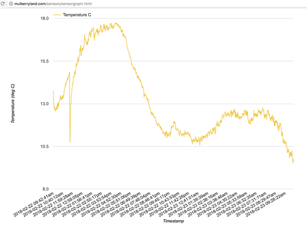
Right now I have a couple of KSD9700 temperature switches. It's rated at 15C, but the hysteresis seems to give it +/- 3 degrees. So it fluctuates all the way from 12 to 18 degrees. And the two I have vary widely in their behaviour, which is probably a symptom of a cheap eBay purchase. But it does the trick for the most part.

I've also seen KSD301, but they look to be much bigger. Not sure if their behaviour is similar.


These Texas Instruments ones seem to be ideal: TMP709, so I'm planning to pick up a few of those. They appear to have a much smaller hysteresis (2 degrees), which means much less temperature fluctuation.


Maxim also has some: MAX6501 that look to be the same kind of thing.


It looks like I can combine those with a transistor to power the 5v heater.

Both are smd, so a small PCB could hold all that's needed in a tiny footprint.


I'm trying to keep things really simple, so I'm trying to avoid using a microcontroller + separate sensor etc. Although I recall the very first of the TI Launchpads came with a chip with a built-in temperature sensor that was part of their demo. But that does require each chip to be programmed, which adds complexity.


Am I missing anything really easy and obvious? Or maybe something less obvious but much more ideal?


ps, does 2 degrees hysteresis mean it would be 15 +/- 2 = 13 to 17 degrees, or is the 2 the sweep from high to low, ie 14 to 16 degrees?


Thanks!

-Nico

  • Sign in to reply
  • Cancel

Top Replies

  • jc2048
    jc2048 over 7 years ago +4
    Look at section 8.2.3 of the TMP709 datasheet. It shows a diagram of the operation on the 10C hysteresis setting. The hysteresis is the width of the band. The temperature 'set point' that you program with…
  • jw0752
    jw0752 over 7 years ago +4
    Hi Nico, One aspect that is often overlooked which is a factor in hysteresis is the coupling between the heater, the sensor, and the target environment. For example a well powered high mass heater will…
  • ntewinkel
    ntewinkel over 7 years ago in reply to genebren +2
    Thanks Gene, Yes, it's very small. It's using a USB hand warmer powered by a dual-port cell phone charger, and it's wrapped in insulation. Sorry, at this point I can't give too much specific details yet…
  • jc2048
    jc2048 over 7 years ago

    Look at section 8.2.3 of the TMP709 datasheet. It shows a diagram of the operation on the 10C hysteresis setting.


    The hysteresis is the width of the band. The temperature 'set point' that you program with a resistor is the top (not the middle, as you might expect). So if you program 16C and select the 2C hysteresis, you should get a band of 14 to 16.

    • Cancel
    • Vote Up +4 Vote Down
    • Sign in to reply
    • Cancel
  • genebren
    genebren over 7 years ago

    Nico,


    Hopefully you are heating a 'very' small area.  Current limits on USB are not going to leave you with too much heat.  Given the following statement of USB current limits, you are going to have somewhere between 2.5 and 7.5W of heater.  Not a lot of heat to work with. Hopefully enough.  Good luck!


    "In the USB 1.0 and 2.0 specs, a standard downstream port is capable of delivering up to 500mA (0.5A); with USB 3.0, it moves up to 900mA (0.9A). The charging downstream and dedicated charging ports provide up to 1,500mA (1.5A)."


    Gene

    • Cancel
    • Vote Up +1 Vote Down
    • Sign in to reply
    • Cancel
  • jw0752
    jw0752 over 7 years ago

    Hi Nico,

    One aspect that is often overlooked which is a factor in hysteresis is the coupling between the heater, the sensor, and the target environment. For example a well powered high mass heater will always overshoot the target temperature. In exchange it will have stability due to its mass. A small mass heater can react more quickly but has its own short comings. Take a good look at the physics of the environment that you want to heat and how you are coupling the heater to that environment as well as placement of the sensor to minimize the hysteresis.

    John

    • Cancel
    • Vote Up +4 Vote Down
    • Sign in to reply
    • Cancel
  • ntewinkel
    ntewinkel over 7 years ago in reply to genebren

    Thanks Gene,


    Yes, it's very small. It's using a USB hand warmer powered by a dual-port cell phone charger, and it's wrapped in insulation. Sorry, at this point I can't give too much specific details yet.


    It's actually quite amazing how roughly 1 amp of power (= 5 watts, right?), combined with good insulation, is more effective than older methods.


    Here's a graph, which shows the heater is having a good effect, switched with the KSD9700, but I think the insulation could use some work!

    I'll add a blog post soon about the ESP-01 data logger I set up to gather that data. ps, that url is still live, and showing the other same setup which is not nearly as neat a graph.

    image

    • Cancel
    • Vote Up +2 Vote Down
    • Sign in to reply
    • Cancel
  • ntewinkel
    ntewinkel over 7 years ago in reply to jc2048

    Thank you for explaining that, Jon!

    I went over that whole document a few times to figure out how the chip works, but that picture never made sense to me until you explained it!


    -Nico

    • Cancel
    • Vote Up +2 Vote Down
    • Sign in to reply
    • Cancel
  • ntewinkel
    ntewinkel over 7 years ago in reply to jw0752

    Hi John!


    The heater is a USB hand warmer. The sensor/switch is a KSD9700 bimetal. The environment is a small insulated area containing liquid.


    >placement of the sensor to minimize the hysteresis.


    Thank you for that, I do think that might be the issue I'm seeing with the second setup. I put the USB-handwarmer heater and the sensor in the same relative position as in setup 1 (see graph replied to Gene above), but I wonder if maybe the insulation is separating them better in the first setup.


    This (graph below) is what's happening in the second setup that is causing me to wonder about the second KSD9700, but you might be right about placement. I think I'll try moving the temperature probe (for the graph data) to right beside the temperature switch to see if that changes the numbers.

    The above graph for setup1 has a roughly 1-hour cycle. Setup2 seems to have a roughly 12 hour cycle, and it looks like the heater is on and off a lot.

    image

    edit, ps: that dip at the start is when the whole setup (heating and data logging) was accidentally unplugged for 25 minutes image


    Thanks,

    -Nico

    • Cancel
    • Vote Up +2 Vote Down
    • Sign in to reply
    • Cancel
  • ntewinkel
    ntewinkel over 7 years ago in reply to ntewinkel

    Aha! I just went out to more precisely place the temperature probe used for logging, and noticed I had it jammed between the container and the temperature switch. sigh. so basically the switch was using an indirect temperature, which might explain the fluctuations.


    I've repositioned the probe to be right beside the switch now, so I'm hoping for better numbers.

    Data has been reset.

    Stay tuned for the live action as the numbers roll in minute by minute!


    http://mulberryland.com/sensors/sensorgraph.html


    Hmm, at 6 degrees it's not looking very good so far... I better check that the heater is still plugged in.


    For science!


    edit: yes looks like heater wasn't plugged in properly. funny you can see where I adjusted it in the graph image

    edit2: sigh. it doesn't look any better. I'm thinking the KSD9700 is faulty and my previous "unplug-replug" maybe shook it enough to briefly turn it on.


    -Nico

    • Cancel
    • Vote Up +2 Vote Down
    • Sign in to reply
    • Cancel
  • ntewinkel
    ntewinkel over 7 years ago

    ps, My application is specific and limited, but the same technology appears to be used for things like outdoor cameras to keep (relatively small) enclosures and the contained equipment dry and warm, for example on highway and ski web cameras (where it also keeps the lenses from fogging up).

    • Cancel
    • Vote Up +2 Vote Down
    • Sign in to reply
    • Cancel
element14 Community

element14 is the first online community specifically for engineers. Connect with your peers and get expert answers to your questions.

  • Members
  • Learn
  • Technologies
  • Challenges & Projects
  • Products
  • Store
  • About Us
  • Feedback & Support
  • FAQs
  • Terms of Use
  • Privacy Policy
  • Legal and Copyright Notices
  • Sitemap
  • Cookies

An Avnet Company © 2025 Premier Farnell Limited. All Rights Reserved.

Premier Farnell Ltd, registered in England and Wales (no 00876412), registered office: Farnell House, Forge Lane, Leeds LS12 2NE.

ICP 备案号 10220084.

Follow element14

  • X
  • Facebook
  • linkedin
  • YouTube