


Table of Contents
Introduction
A very long time ago (7 years ago) I tried to build a digital PCB inspection microscope, using a camera and lens connected to a computer. While it worked, there was plenty of room for improvement. This new blog post tries to tackle that. The new microscope is (I believe) better in every way, physically and functionally, and is faster, more versatile too, and its software has new features, some of which I have not seen on ready-made microscopes.

I had the chance to experiment during the past few days, and this blog post (and another if I can squeeze it in on time) will be the last couple of projects from me for 2022. There is a lot of room for improvement, but it is worth documenting now since I have reached a semi-decent point. There is a video explanation of one of the features here (direct YouTube link):
New Features
I’ve prototyped three features so far.
Cross-Hairs
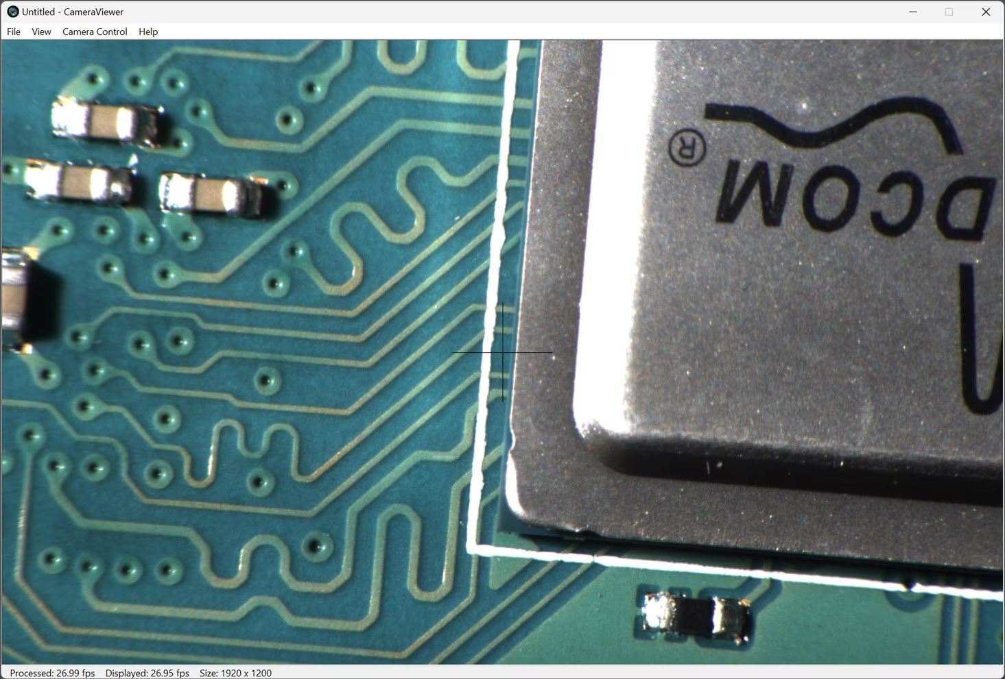
It’s self-explanatory! The video image has cross-hairs on it, which is very handy when zooming in/out. You can physically position the item of interest under the cross-hairs, and then quickly change zoom. Despite its simplicity I really like this feature. The screenshot below (Raspberry Pi board) shows the faint cross-hairs in the center.
Quick Record
The system records uncompressed video. I created a little floating menu with recording controls, but also implemented keyboard shortcuts. If the number 1 key is pressed, then 1-second of video is recorded. Pressing 5 records 5 seconds. Pressing 0 records 10 seconds. These will be handy for quicky recording snippets of video. The file sizes are absolutely huge, but are easily compressed later on using free “Handbrake” software. I didn’t see any urgent need compress in real-time, because there is always plenty of video screen capture options if the direct uncompressed format was not desired.
It would be nice to implement a history buffer, so that the software records all the time, and pressing the record button would then capture the previous second as well. I might try to implement that at later date.
Overlay/Optical Alignment
This feature is used to take a snapshot and insert itself back into the image. I have a potential use for this. The idea is, you could place a surface-mount device (SMD) integrated circuit (QFN or BGA style chip would be a possible candidate) upside-down in front of the camera, and hit the letter O key to turn on the Overlay mode. As soon as the key is pressed, the snapshot of the SMD IC is taken and dimmed and permanently displayed as if it were a ghost image. Now you can remove the IC and place the circuit board in front of the camera instead, and align the ghost image IC pads on top of the actual PCB pads. Once that is done, you can place the SMD IC the right-way around onto the PCB, and align the ghost outline of the IC with the real IC.
The animation below shows how the feature could be used.

I’ve no idea how well or how badly this will work in practice when soldering, but at least it can now be tried out. It needs some improvement - I'd like to use edge enhancement on the overlay. (Edit: I've now tried that, using OpenCV, here is an example image, but I still need to work on this further):

In the past, there were systems that optically (not digitally!) combined board and chip views for the observer, for BGA IC alignment, but they cost 4- or 5-figure sums. This project has a low-3-figure sum.
The good thing is that this overlay feature doesn’t seem to impact performance at all, it all runs in real-time with no noticeable latency (I will measure it sometime).
What was wrong with the old project?
To recap, the old digital PCB Microscope project made use of a snooker-cue-chalk sized camera with a C-mount lens. Together, the camera and lens would allow focusing from a distance, to see a printed circuit board and components close-up. The video image was sent via Ethernet from the camera, to the computer. That computer was a single board computer known as Gizmo 2, which has long been obsolete, and it wasn’t very powerful anyway. I could only achieve 10 frames per second with the old project, whereas the new one can run at the full camera supported rate (27 Hz in my case).

Another issue with the old project was that I didn’t sort out the lighting problems very well at the time, relying on a desk-lamp. Yet another problem was that I was relying on quite slim (and expensive) metal rods, and vibrations would result if the table was knocked. I wanted to re-do the mechanics.
Finally, the software was not great. There were no handy features.
I hopefully learned from some of my mistakes, and tried to improve things with the project described here.
Keep what Works
The camera, despite being 7 years old, is still not bad. It can theoretically achieve 27 frames per second of uncompressed video at 1920 x 1200 resolution, which is more than enough for me. If I need higher resolution, I can use a normal photography camera. I didn’t upgrade the camera. It is model BFLY-PGE-23S2C-CS by FLIR (it’s not a thermal camera, it’s a normal camera!).
The lens seemed fine too. It is a zoom lens with macro capability, Computar model MLH-10X. There are plenty of other C-mount microscope lenses on ebay/Amazon, they would probably all produce results that are usable. I decided not to replace the lens either.
The screenshot below shows the type of image the camera and lens is capable of, provided there is good lighting. This photo is near-vertical, because my current tripod cannot handle an entirely vertical setup.

Use Standard Photography Mounts
Photography hardware is often cheaper than microscope or lab optical mounts, so I ditched the metal rods, and switched to SmallRig stuff. If you’re unfamiliar with it, it is basically an ecosystem of aluminium and steel components a bit like Lego, that can assemble to connect photography gear together.
I re-used an old plastic camera mount which I’d created for the older project (3D printing could also be an option, but I don’t have that capability), and just drilled a few more holes, to accept SmallRig components. Now I can position the camera and lens at any angle, by merely adjusting a desktop tripod or swapping out for a different tripod. The current tripod I’m using doesn’t allow me to position the camera entirely vertically without toppling over, but I can get quite close. I will re-think and choose a different tripod or clamp at a later date. I’m already happy that vibration is pretty much eliminated with the SmallRig parts.
Improved Lighting
The large clip-on lamp had issues, it had to go.
There’s a love-hate aspect to ring lights. They can produce a lot of glare depending on the angle that the light hits the object being viewed. Also, they can produce an unappealing reflection of the shape of the ring, but that’s not as important for a PCB inspection microscope perhaps. What I really like about ring lights is that they can simplify things; just a single ring light can be sufficient for a lot of tasks.
It’s still not as great as multiple separated lights (on say goosenecks), which can always be placed in more optimal positions, but the ring light is less fiddly.
I went for a pretty large ring light with overall diameter of about 130 mm, in the hope that the light would hit objects at an angle. It does, but it’s still not great. I think a long-range microscope is better with gooseneck lighting.
If you wanted to go gooseneck, then this sort of device could be useful; it has a cold-shoe fitting, and there are SmallRig components that can fit that. I am likely to upgrade to a gooseneck lighting method at some point, as soon as I can find a decent option.

Build Software
I was happy that things were coming together on the mechanical front, but I needed to address the software too. The old microscope project used Ubuntu Linux. I figured I should move to Windows, because I don’t normally run desktop Linux (only on some servers), and since I would need a monitor for viewing the images/video, I may as well run the software on the same environment that I use day-to-day, and save having to do things like video streaming or remote desktop/VNC.
Another advantage to using Windows instead of Ubuntu, is that I could use a Windows tablet in future, and free up desk space if the laptop or keyboard wasn’t essential.
Fortunately the FLIR camera is supported by a nice software development kit (SDK) that is available for Windows, so I brought it up in Visual Studio and compiled one of the demo programs, and then got to work improving it for my needs by adding the features mentioned earlier. I was excited that I could completely customize stuff, although I’m no desktop app developer so I’d be learning as I go.
I was happy to see that video speed reached its maximum (27 frames per second, which is the limit of the camera I’m using), and latency was not noticeable (I will measure it at some point). This performance was great! and it was with a several-year-old Windows laptop computer. I still need to enhance the software, and try to make it compatible with different resolution cameras too.
Summary
A new improved digital PCB microscope was assembled, mostly from ready-made components with very little mechanical work. I spent a bit of time working on the software aspects, and the project supports features that are hopefully relevant for PCB work. I'd also like to add some basics like a timestamp or timer overlay.
I need to find time to work on this project further, since it is very proof-of-concept currently. It would be interesting to hear about ideas for future features/improvements too.
Thanks for reading!


