element14 Community
element14 Community
    Register Log In
  • Site
  • Search
  • Log In Register
  • About Us
  • Community Hub
    Community Hub
    • What's New on element14
    • Feedback and Support
    • Benefits of Membership
    • Personal Blogs
    • Members Area
    • Achievement Levels
  • Learn
    Learn
    • Ask an Expert
    • eBooks
    • element14 presents
    • Learning Center
    • Tech Spotlight
    • STEM Academy
    • Webinars, Training and Events
    • Learning Groups
  • Technologies
    Technologies
    • 3D Printing
    • FPGA
    • Industrial Automation
    • Internet of Things
    • Power & Energy
    • Sensors
    • Technology Groups
  • Challenges & Projects
    Challenges & Projects
    • Design Challenges
    • element14 presents Projects
    • Project14
    • Arduino Projects
    • Raspberry Pi Projects
    • Project Groups
  • Products
    Products
    • Arduino
    • Avnet Boards Community
    • Dev Tools
    • Manufacturers
    • Multicomp Pro
    • Product Groups
    • Raspberry Pi
    • RoadTests & Reviews
  • Store
    Store
    • Visit Your Store
    • Choose another store...
      • Europe
      •  Austria (German)
      •  Belgium (Dutch, French)
      •  Bulgaria (Bulgarian)
      •  Czech Republic (Czech)
      •  Denmark (Danish)
      •  Estonia (Estonian)
      •  Finland (Finnish)
      •  France (French)
      •  Germany (German)
      •  Hungary (Hungarian)
      •  Ireland
      •  Israel
      •  Italy (Italian)
      •  Latvia (Latvian)
      •  
      •  Lithuania (Lithuanian)
      •  Netherlands (Dutch)
      •  Norway (Norwegian)
      •  Poland (Polish)
      •  Portugal (Portuguese)
      •  Romania (Romanian)
      •  Russia (Russian)
      •  Slovakia (Slovak)
      •  Slovenia (Slovenian)
      •  Spain (Spanish)
      •  Sweden (Swedish)
      •  Switzerland(German, French)
      •  Turkey (Turkish)
      •  United Kingdom
      • Asia Pacific
      •  Australia
      •  China
      •  Hong Kong
      •  India
      •  Korea (Korean)
      •  Malaysia
      •  New Zealand
      •  Philippines
      •  Singapore
      •  Taiwan
      •  Thailand (Thai)
      • Americas
      •  Brazil (Portuguese)
      •  Canada
      •  Mexico (Spanish)
      •  United States
      Can't find the country/region you're looking for? Visit our export site or find a local distributor.
  • Translate
  • Profile
  • Settings
Test & Tools
  • Technologies
  • More
Test & Tools
Blog Building an Event Counter / Rotary Measurement device for $15
  • Blog
  • Forum
  • Documents
  • Files
  • Members
  • Mentions
  • Sub-Groups
  • Tags
  • More
  • Cancel
  • New
Join Test & Tools to participate - click to join for free!
  • Share
  • More
  • Cancel
Group Actions
  • Group RSS
  • More
  • Cancel
Engagement
  • Author Author: shabaz
  • Date Created: 13 Sep 2013 3:27 PM Date Created
  • Views 1700 views
  • Likes 1 like
  • Comments 4 comments
  • kinetis_l_series
  • rotary_encoder
  • kinetis_l
  • test_and_measurement_equipment
  • frdm
  • avago
  • measurement
  • frdm-kl46z
  • freescale_semiconductor
  • freescale_kl46z
  • test_tools
  • bourns
  • test&measurement
Related
Recommended

Building an Event Counter / Rotary Measurement device for $15

shabaz
shabaz
13 Sep 2013

I recently needed a quick device to count pulses and measure distance/rotation and I thought it worth documenting in case others have similar requirements.


If you’re building something mechanical (e.g. a robot) then this could become a standard part of your toolkit – it will allow you to see exactly how many degrees your servo turned, or how far the motor travelled. I used a FRDM-KL46Z board because it is low cost ($15) and has everything on-board including the LCD display. So no soldering needed (Apart from the headers).


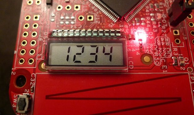
The LCD display, and the built-in switches (to control digit scrolling and counter reset) were the things that drove this to be the ideal board for this project.

image


Example uses for it include: Bike distance meter, X/Y/Z indication of mechanical travel, counting of error/anomaly events, measuring angles. The possibilities are extensive. It can be connected to switches, rotary encoders or other sensors and should run to a reasonably high speed (multiple MHz) although the limit has not been measured yet.

If you’re not familiar with the FRDM-KL46Z board, it is really easy to use; plug the board into your laptop, and it appears as a USB file system. Then just drag the built code (attached to this post) into the FRDM board and it will automatically self-program!

The source code is attached in case you wish to make any modifications.


Here is a video of a quick experiment with angle measurement (in steps of 0.7 degrees):

You don't have permission to edit metadata of this video.
Edit media
x
image
Upload Preview
image

Detailed Description

image

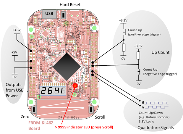
The application is really quite simple; it uses a total of 4 pins on the board as shown in the diagram above. Two are used as edge-triggered counters (rising and falling edge, so you can choose whichever you need; they could be wired to a switch or some sensor) and the other two pins are programmed for a quadrature input signal capability, so that up/down counting is possible (e.g. using rotary encoders for clockwise/anticlockwise counting up/down).


There are two built-in buttons on the FRDM board, and one is used to reset the counter to zero, and the other is used to scroll the digits (if the count exceeds 9,999) to see a total of 8 digits (i.e. 99,999,999).


All you need is to download the attached zip file, extract the counter.srec file and drag it to the FRDM board. The board can be powered from USB or from a battery for portable use. If you wish to compile the code (e.g. to make modifications), use the zip file contents and the information here to see how this is done using CodeWarrior and using Processor Expert. (See notes below if you are compiling the source, so that you have 'additional components' inside Processor Expert).


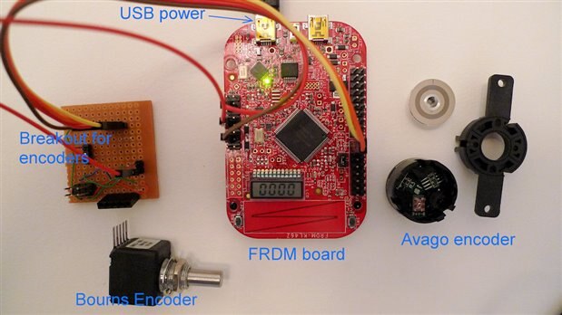
This photo shows the entire setup - and some example rotary encoders.

image

How to use the Application

As mentioned, it can be dragged-and-dropped into the FRDM board over a USB cable and the software will become programmed into the board. Then all you need to do is connect a switch or sensor to one of the pins on the board.

Pulse Counting

For counting pulses, there are two options; positive or negative edge triggered. A pull-down resistor (of value about 4.7k) may be needed if you’re using the positive-edge triggered input option.

All input pins are configured with internal pull-ups so technically no external pull-up resistor is needed for the negative edge trigger input although it is shown on the diagram; you could omit it. Assume 20k resistance for the internal pull-ups, so the external pull-down resistor for the positive edge trigger input needs to be about 4.7k (or disable the internal pull-up in the code, or use a buffer).

Rotary Encoder Feature

The two pins A and B on the diagram are dedicated for connecting to devices like rotary encoders. As an example, the board was connected to a 128-cycle per revolution rotary encoder. The actual count registered per cycle is 4, so a 128 cycle per revolution encoder will provide a value of 512 if it is rotated 360 degrees, i.e. a resolution of 0.7 degrees is achieved with this example encoder.

It was tested with a Bourns rotary encoder; other examples that would work include the excellent Avago HEDS encoders (I have not had a chance to test this yet).

The signals are captured via interrupts, and should function at a high speed although this remains to be tested.

If your rotary encoder offers up 5V logic levels then they will need to be converted to 3.3V logic levels (either using resistors or preferably logic level converters for high speed).

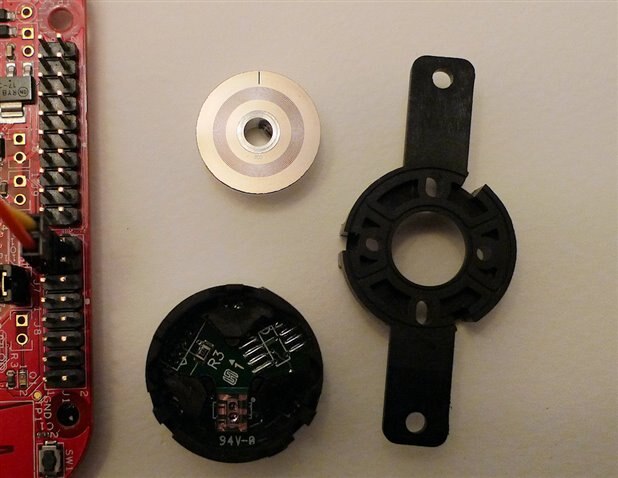
The photo here shows a close-up of an Avago encoder - the wheel can be directly attached to any shaft and run at very high speeds.

image

Next Steps

The code today is useful, but it would be great to add more functionality. It would be great to see what ideas and adapted code people come up with (please share it if you can!).


Since the board is low cost, I intend to keep it for pulse/rotary counter purposes and use another FRDM board for voltage measurement purposes; they also have a built-in ADC, so the possibility exists to create some great test tools for (say) recording a peak analoge quantity over a long period of time in a location unsuitable for leaving a more expensive device.


Code Details

This information is really just for reference - only useful if you wish to make any code changes.


Processor Expert:

Processor Expert has a set of features, but it is possible to increase them for greater functionality.

I had installed a set of features from this site - but  use this direct link to the zip file.

This gives you some great features, I used a WAIT component from there to provide a sleep rather than a for() loop.

By the way, when you download the file from that site, you may find you cannot extract it. The Windows built-in unzip capability did not work for me. I had to use 7-zip to extract it.

When you extract, it gives two files in the PEupd sub-folder in the zip file.

These can be imported into CodeWarrior using the menu Processor Expert->Import Components.


Pin detail:

PORTC_10 – Rotary Encoder ‘A’ input
PORTC_11 – Rotary Encoder ‘B’ input
PORTC_13 – Falling edge triggered
PORTC_16 – Rising edge triggered
SW1 (PORTC_3) [Bit2] – Read high digits (when red LED is lit)
SW3 (PORTC_12) [Bit3] – Set Counter to zero
RED_LED (PORTE_29) [Bit1] – When lit, the count has exceeded 4 digits (9999)
GREEN_LED (PORTD_5) [Bit4] – not used yet


Things to manually change after Processor Expert (PE) modifications, to enable pull-ups:

I couldn't see how to enable pull-ups from the Processor Expert components, so I directly modified the PE auto-generated C code.

Not ideal, but it worked for my immediate needs. Note that if you subsequently add more components using PE, then you will need to re-enter these changes because PE will wipe it from the auto-generated code:


GPIO1.c approx. lines 178, 185, 192 and 199 (i.e. for PCR10, PCR11, PCR13 and PCR16), insert

| 0x03

In files Bit2.c and Bit3.c around line 112, insert

| 0x03


So, an example would be (notice the |0x03 at the end):

PORTC_PCR13 = (uint32_t)((PORTC_PCR13 & (uint32_t)~(uint32_t)(
                 PORT_PCR_IRQC(0x05)
                )) | (uint32_t)(
                 PORT_PCR_ISF_MASK |
                 PORT_PCR_IRQC(0x0A)
                )) | 0x03;   

Attachments:
counter_source_code.zip
counter_executable.zip
  • Sign in to reply
  • shabaz
    shabaz over 11 years ago

    Hello Tom,


    I'm so sorry, it looks like I missed out a step :-(

    Processor Expert has a set of features, but it is possible to increase them for greater functionality.

    I had installed a set of features from this site - but  use this direct link to the zip file (about 23 MByte).

    This gives you some great features like a WAIT1_waitms. If that is the only one that is missing, in theory you could replace it with just a 'for' loop (e.g. a loop of 100000), the time period is non-critical, and it will still work. The best way is to download the additional features from that site, and the wait feature will provide a sleep.


    By the way, when you download the file from that site, you may find you cannot extract it. The Windows built-in unzip capability did not work for me. I had to use 7-zip to extract it.

    When you extract, it gives two files in the PEupd sub-folder in the zip file.

    These can be imported into CodeWarrior using the menu Processor Expert->Import Components.


    I will add this information to the page.


    By the way, since you are building the code, don't forget after you are done with Processor Expert changes, when you compile, afterwards, add the | 0x03 mentioned above (an example is pasted below) and compile again. This is to enable the pull-ups (otherwise you will need external pull-ups). The Processor Expert components that I used did not have a pull-up capability. If I add more components from Processor Expert, then the | 0x03 gets wiped since technically this is not advisable to modify the auto-generated code. I'm sure it is resolvable, but I didn't spend time on that.


    PORTC_PCR13 = (uint32_t)((PORTC_PCR13 & (uint32_t)~(uint32_t)(

                     PORT_PCR_IRQC(0x05)

                    )) | (uint32_t)(

                     PORT_PCR_ISF_MASK |

                     PORT_PCR_IRQC(0x0A)

                    )) | 0x03;   

    • Cancel
    • Vote Up 0 Vote Down
    • Sign in to reply
    • More
    • Cancel
  • Former Member
    Former Member over 11 years ago

    Line 134 in processorexpert.c gave me "undefined reference to WAIT1_waitms.  Seems the function isn't declared anywhere.

    • Cancel
    • Vote Up 0 Vote Down
    • Sign in to reply
    • More
    • Cancel
  • shabaz
    shabaz over 11 years ago in reply to mcb1

    Thanks!

    Freescale are really producing some great boards - I wonder what their next FRDM board will be like :-)

    • Cancel
    • Vote Up 0 Vote Down
    • Sign in to reply
    • More
    • Cancel
  • mcb1
    mcb1 over 11 years ago

    Shabaz

    This is a great little tool, with many uses for quick and easy applications.

    Thanks


    Mark

    • Cancel
    • Vote Up 0 Vote Down
    • Sign in to reply
    • More
    • Cancel
element14 Community

element14 is the first online community specifically for engineers. Connect with your peers and get expert answers to your questions.

  • Members
  • Learn
  • Technologies
  • Challenges & Projects
  • Products
  • Store
  • About Us
  • Feedback & Support
  • FAQs
  • Terms of Use
  • Privacy Policy
  • Legal and Copyright Notices
  • Sitemap
  • Cookies

An Avnet Company © 2025 Premier Farnell Limited. All Rights Reserved.

Premier Farnell Ltd, registered in England and Wales (no 00876412), registered office: Farnell House, Forge Lane, Leeds LS12 2NE.

ICP 备案号 10220084.

Follow element14

  • X
  • Facebook
  • linkedin
  • YouTube