element14 Community
element14 Community
    Register Log In
  • Site
  • Search
  • Log In Register
  • About Us
  • Community Hub
    Community Hub
    • What's New on element14
    • Feedback and Support
    • Benefits of Membership
    • Personal Blogs
    • Members Area
    • Achievement Levels
  • Learn
    Learn
    • Ask an Expert
    • eBooks
    • element14 presents
    • Learning Center
    • Tech Spotlight
    • STEM Academy
    • Webinars, Training and Events
    • Learning Groups
  • Technologies
    Technologies
    • 3D Printing
    • FPGA
    • Industrial Automation
    • Internet of Things
    • Power & Energy
    • Sensors
    • Technology Groups
  • Challenges & Projects
    Challenges & Projects
    • Design Challenges
    • element14 presents Projects
    • Project14
    • Arduino Projects
    • Raspberry Pi Projects
    • Project Groups
  • Products
    Products
    • Arduino
    • Avnet Boards Community
    • Dev Tools
    • Manufacturers
    • Multicomp Pro
    • Product Groups
    • Raspberry Pi
    • RoadTests & Reviews
  • Store
    Store
    • Visit Your Store
    • Choose another store...
      • Europe
      •  Austria (German)
      •  Belgium (Dutch, French)
      •  Bulgaria (Bulgarian)
      •  Czech Republic (Czech)
      •  Denmark (Danish)
      •  Estonia (Estonian)
      •  Finland (Finnish)
      •  France (French)
      •  Germany (German)
      •  Hungary (Hungarian)
      •  Ireland
      •  Israel
      •  Italy (Italian)
      •  Latvia (Latvian)
      •  
      •  Lithuania (Lithuanian)
      •  Netherlands (Dutch)
      •  Norway (Norwegian)
      •  Poland (Polish)
      •  Portugal (Portuguese)
      •  Romania (Romanian)
      •  Russia (Russian)
      •  Slovakia (Slovak)
      •  Slovenia (Slovenian)
      •  Spain (Spanish)
      •  Sweden (Swedish)
      •  Switzerland(German, French)
      •  Turkey (Turkish)
      •  United Kingdom
      • Asia Pacific
      •  Australia
      •  China
      •  Hong Kong
      •  India
      •  Korea (Korean)
      •  Malaysia
      •  New Zealand
      •  Philippines
      •  Singapore
      •  Taiwan
      •  Thailand (Thai)
      • Americas
      •  Brazil (Portuguese)
      •  Canada
      •  Mexico (Spanish)
      •  United States
      Can't find the country/region you're looking for? Visit our export site or find a local distributor.
  • Translate
  • Profile
  • Settings
Test & Tools
  • Technologies
  • More
Test & Tools
Blog Building Kelvin (4-Wire) Test Leads
  • Blog
  • Forum
  • Documents
  • Files
  • Members
  • Mentions
  • Sub-Groups
  • Tags
  • More
  • Cancel
  • New
Join Test & Tools to participate - click to join for free!
  • Share
  • More
  • Cancel
Group Actions
  • Group RSS
  • More
  • Cancel
Engagement
  • Author Author: shabaz
  • Date Created: 12 Sep 2018 6:00 PM Date Created
  • Views 13444 views
  • Likes 17 likes
  • Comments 27 comments
  • kelvin measurement
  • 2-wire measurement
  • passive_featured
  • 4 wire measurement
  • kelvin
Related
Recommended

Building Kelvin (4-Wire) Test Leads

shabaz
shabaz
12 Sep 2018

Introduction

This short blog post discusses an attempt to make test leads for hopefully better measurements!

image


Measuring small resistances is really difficult with the usual 2-wire measurement with multimeters. The multimeter will measure the resistance of the leads as well as the resistance-under-test. Although this could in theory be nulled out, the result can still be poor because the connection still depends on the variable resistance between the probes and the device, i.e. contact resistance. This can vary by tens of milliohms, or a lot worse (hundreds of milliohms). It’s not possible to easily apply a precise, unchanging amount of force using the test probes.

image


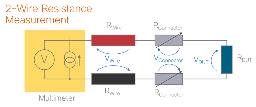
How can it be solved? The multimeter passes some current through the device, and measures the voltage to derive the resistance using R=V/I. But, that voltage happens to be the sum of the voltage across the device under test, but also the voltage across the red and black test leads (because the current is passing through them too and developing a potential across them), as well as the connectors or contacts. It follows that if a separate voltmeter was used to measure the voltage using two separate probes, the measured voltage would not include the voltage across the test leads and contact resistance. That’s the solution – find a bench meter with 4 connections on it. This solution is a 4-wire measurement (also known as a Kelvin measurement). The diagram below shows how it works. The thickened wires carry the driving current to make the measurement. The voltmeter is of a very high impedance and no significant current passes through the wires directly attached to it. With this method however, it is awkward to have 4 test leads or test clips. It’s a messy amount of clips and wires.

image


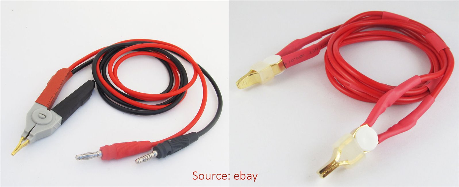
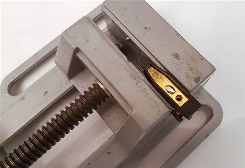
But, there are some nice reasonable cost test clipstest clips with dual isolated metal contacts that can be used instead - they will grip the wire of the device under test on both sides, with a separate connection. They are very fancy gold-plated parts, for about £8.50 / $11 USD each. I also picked up some nice gold-plated banana plugs in redbanana plugs in red and blackblack, and set about assembling it all together.


Note that for cheaper clips, there is ebay, but word on the street is that some may be constructed of aluminium with some gold coating. It shouldn't be an issue, but it is a judgement call if that is ok. I've been bitten in the past by strange gold plating on connectors that darken or discolour over time, so I avoid any gold-plated connectors from ebay. I am only going to be making one or two sets of these for my personal use, so I want them to last, so I went with the known material clips.


There are also ready-made test leads from ebay, that cost under $10, so that’s another option. However they may require some modifications (see the strange photos below). In any case, sometimes it’s nice hand-assembling stuff to your precise requirements.

image


Building the Leads

The red red and black wiresblack wires had silicone insulation for flexibility. The wire is 5 metres long; I only used one metre, so there is plenty left over to make various other test leads too.

image


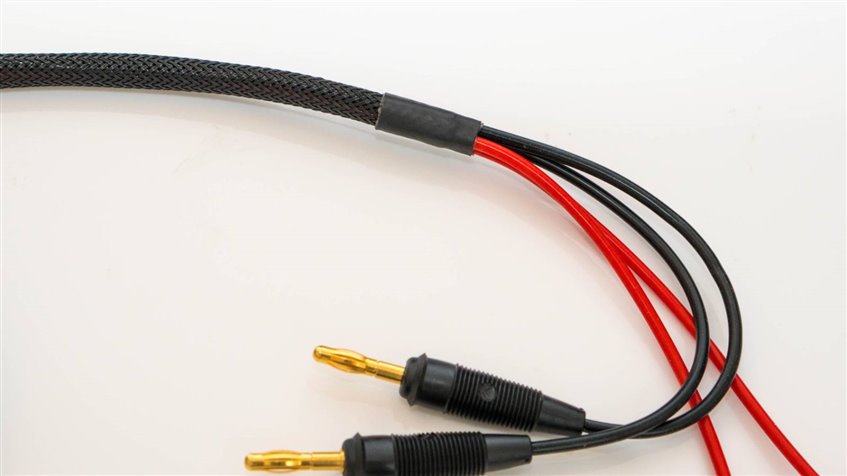
Since 4 wires will tangle on the desk, plastic braidplastic braid could be an option. It does reduce the flexibility a bit, but not much. I decided to run with it. Adhesive lined heat shrink tubingAdhesive lined heat shrink tubing was applied to stop it fraying. To get the braid over the wires easily, I taped the wires at 15-cm spacing, and removed the tape when the braid was pushed close to it.

image


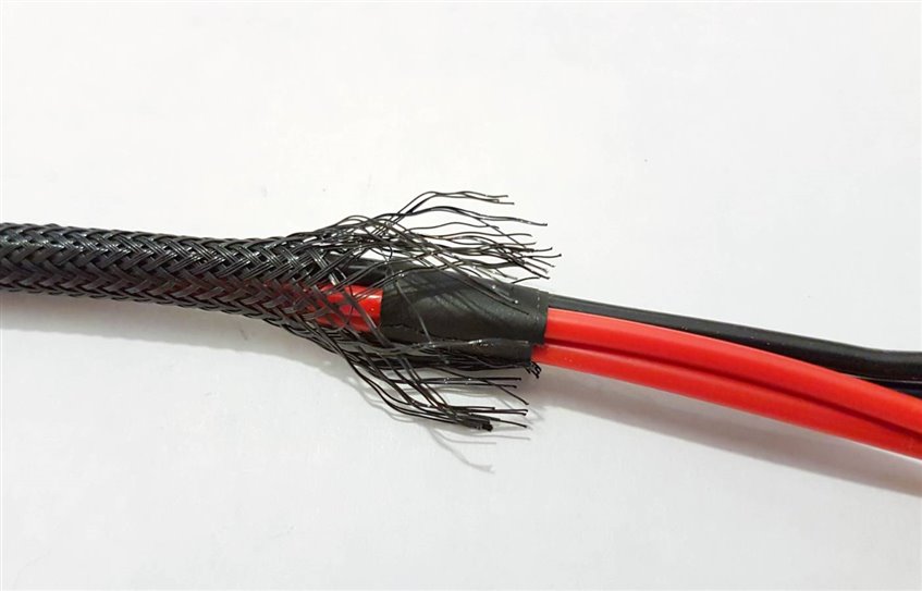
The braid could melt while using the heat-shrink tubing, so I protected it with some paper tape (or use Kapton tape) while applying the heat gun, and it worked fine.

image


The clips come with screw terminals, but it felt awkward putting the stranded wire inside there. I did consider using a ring terminal, but in the end it seemed it could be easier to just solder the wires. The plastic clips didn’t feel too soft, so I felt they could take the temporary heat from a soldering iron.

image


The screws play a structural role with these clips though. Without them, the metal portion of the clips slide around. With hindsight, I would have replaced them with 3mm grub screws, but in my case, I just left the supplied screws in there, and it means the wire insulation has to pass over the screw head. It is not a big deal, and provides some grippy area to hold the clips actually!

image


Since the clips are gold-plated, they are very easy to solder onto. I used a 3mm soldering iron bit and turned up the heat to 350 degrees C, since the aim was to get the heat quickly onto the clip, and finish the soldering task in 5-10 seconds if possible, to reduce the risk of damaging the plastic. It worked fine. Three hands are needed though. I used a flat blade screwdriver to gently press the wire strands against the clip while I soldered it.


Summary

I was happy that with little effort, I've got reasonable 4-wire measurement capability. I have not used them much yet, but as a quick test, I took a length (about 60cm, I didn’t measure it) of 0.15mm diameter enamelled copper wire and stripped the ends, and measured it with the clips. It was 798 milliohms. In contrast the handheld multimeter was measuring 2 or 3 ohms, fluctuating all over the place.


Next I folded it in half and cut it and re-measured one length using the clips, and it was 398 milliohms, so it’s clearly functioning, allowing resistance measurements without the inaccuracies of the 2-wire method.


Overall, these test leads cost under £40 for all parts, which is not bad – and costs can be further reduced by using old test lead wire : )

  • Sign in to reply

Top Comments

  • Gough Lui
    Gough Lui over 7 years ago +8
    That's quite a good project - in fact, I should probably build some myself. My excuse for not bothering with 4W mode on most of the instruments boils down to either the sense terminals being at the back…
  • fmilburn
    fmilburn over 7 years ago in reply to three-phase +7
    This might be a fun project to try and make your own meter. I am assuming you could set up a constant current source and then use a microcontroller with a good ADC to measure and display resistance. Not…
  • fmilburn
    fmilburn over 7 years ago +6
    Very nice. Another project added to my list :-)
Parents
  • three-phase
    three-phase over 7 years ago

    Nice blog, 4 wire measurement is definitely more accurate for lower resistance measurements. I use the methodology a lot for measuring winding resistances of rotating plant down to a few milli-ohms and busbar joints down to micro-ohms. Needs an instrument with 4 wire measurement capability to get the most out of it, although sometimes I do use a voltmeter and current meter setup, record the readings and then do the math, although obtaining stable readings can be an issue. I also tend to like to use a reasonably high test current for the apparatus I work on.


    Kind regards

    • Cancel
    • Vote Up +5 Vote Down
    • Sign in to reply
    • More
    • Cancel
  • fmilburn
    fmilburn over 7 years ago in reply to three-phase

    This might be a fun project to try and make your own meter.  I am assuming you could set up a constant current source and then use a microcontroller with a good ADC to measure and display resistance.  Not super accurate maybe but better than a regular multimeter.

    • Cancel
    • Vote Up +7 Vote Down
    • Sign in to reply
    • More
    • Cancel
  • fmilburn
    fmilburn over 7 years ago in reply to fmilburn

    Mechanical Engineers....  I did not stop to think this through before posting :-).  If the DUT is 0.01 ohms and we put say 0.1 amps through it then the voltage drop is 0.001 volts.  And the internal voltage reference of the microcontroller is maybe 1.5V.  This is not trivial.  I am interested in what others think....

    • Cancel
    • Vote Up +5 Vote Down
    • Sign in to reply
    • More
    • Cancel
  • shabaz
    shabaz over 7 years ago in reply to fmilburn

    Hi Frank,

    It's a great idea, it would be a useful project.

    Maybe it is more easier with a panel meter, and then construct just the constant current portion. By the way these ones are surprisingly accurate, although I only did some basic measurements:

    https://www.ebay.co.uk/itm/200925709595?_trksid=p2057872.m2749.l2649&ssPageName=STRK%3AMEBIDX%3AIT

    Or, instead of the DC constant current source, there is an interesting circuit here (PDF):

    http://67.225.133.110/~gbpprorg/mil/cavity/lock/22192533AN306.pdf

    • Cancel
    • Vote Up +5 Vote Down
    • Sign in to reply
    • More
    • Cancel
  • fmilburn
    fmilburn over 7 years ago in reply to shabaz

    Thanks Shabaz,

    Wow - 5 digits for that price is amazing.  The circuit is also interesting and could measure very low resistance.  Milliohm meters can be quite expensive and this might be a good project for the upcoming Test Instrumentation Project14.

    • Cancel
    • Vote Up +5 Vote Down
    • Sign in to reply
    • More
    • Cancel
  • michaelkellett
    michaelkellett over 7 years ago in reply to shabaz

    You could replicate the AD circuit using a micro with built in DAC and ADC (although you would need a buffer amplifier/filter for the DAC output and an amplifier for the analogue signal. The micro can generate the sine wave excitation by DDS and sample the AC signal synchronously - so replacing the AD630 (no small matter since they cost £20 or more in small numbers and you need the micro anyway). If you really want to push the boat out use an STM32H750VBT6 for the micro (16 bit ADC, 400MHz clock 100 pins about £4 for one off).


    Because of the AC coupling nothing special is needed of the amplifiers  - the H750 can easily do DDS at up to 10kHz although I would use a lower frequency than the 1kHz suggested by AD.


    Using a proper diff amp configuration for the input will allow a four terminal connection.


    MK

    • Cancel
    • Vote Up +4 Vote Down
    • Sign in to reply
    • More
    • Cancel
Comment
  • michaelkellett
    michaelkellett over 7 years ago in reply to shabaz

    You could replicate the AD circuit using a micro with built in DAC and ADC (although you would need a buffer amplifier/filter for the DAC output and an amplifier for the analogue signal. The micro can generate the sine wave excitation by DDS and sample the AC signal synchronously - so replacing the AD630 (no small matter since they cost £20 or more in small numbers and you need the micro anyway). If you really want to push the boat out use an STM32H750VBT6 for the micro (16 bit ADC, 400MHz clock 100 pins about £4 for one off).


    Because of the AC coupling nothing special is needed of the amplifiers  - the H750 can easily do DDS at up to 10kHz although I would use a lower frequency than the 1kHz suggested by AD.


    Using a proper diff amp configuration for the input will allow a four terminal connection.


    MK

    • Cancel
    • Vote Up +4 Vote Down
    • Sign in to reply
    • More
    • Cancel
Children
  • shabaz
    shabaz over 7 years ago in reply to michaelkellett

    Hi Michael,


    I hadn't realized the AD. chip was so expensive. Doing it all digitally is a really nice idea! I'm totally new to ST micros, it's impressive what that part can do. The 12-bit DAC built-in is neat - perfect for very high quality signals. It looks like an excellent part for many signal generation/processing test tools.

    • Cancel
    • Vote Up +4 Vote Down
    • Sign in to reply
    • More
    • Cancel
  • fmilburn
    fmilburn over 7 years ago in reply to michaelkellett

    Thanks Michael,


    That is great information.  I will continue looking into this. 

    • Cancel
    • Vote Up +3 Vote Down
    • Sign in to reply
    • More
    • Cancel
element14 Community

element14 is the first online community specifically for engineers. Connect with your peers and get expert answers to your questions.

  • Members
  • Learn
  • Technologies
  • Challenges & Projects
  • Products
  • Store
  • About Us
  • Feedback & Support
  • FAQs
  • Terms of Use
  • Privacy Policy
  • Legal and Copyright Notices
  • Sitemap
  • Cookies

An Avnet Company © 2025 Premier Farnell Limited. All Rights Reserved.

Premier Farnell Ltd, registered in England and Wales (no 00876412), registered office: Farnell House, Forge Lane, Leeds LS12 2NE.

ICP 备案号 10220084.

Follow element14

  • X
  • Facebook
  • linkedin
  • YouTube